Here is the power supply circuit that I built into my pre-amp. It performs very well, and with it I have ~8 microvolts of noise on the amplifier circuit, a number that I don't think anyone would complain about.
However, after doing a bunch more reading since I finalized the design of the PS, I would do things a little differently were I to do it over again. I would drop the IC regulators and substitute mosfet based voltage followers.
Why? The IC regulators have better ripple rejection around the 100-1000Hz range as compared to a follower, but the CRC filter has already dropped the ripple to a few mV already, so both approaches will suffice for ripple rejection purposes. The voltage follower has better rejection and a lower ouput impedance than the IC regulator at high frequencies, where the CRC filter doesn't perform quite as well, so that the follower and CRC filter compliment each other in their properties. Lastly, the voltage follower has a much lower level (~20dB) of self generated noise. I'll post a schematic sometime over the next couple of days of the voltage follower circuit, and for those of you in a hurry, look at Nelsons original BZLS article, and slap the CRC filter in front, cause that's essentially what I'll be posting.
Cheers, Terry
Attachments
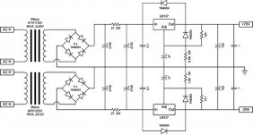
The upper device was an LM317, wasn't it? The 137 is another negative regulator, actually.
How did you happen on 27 ohms as the "R" in your CRC filter? It seems higher than I might have tried.
How did you happen on 27 ohms as the "R" in your CRC filter? It seems higher than I might have tried.
Jeez, I'd better stop posting schematics for a bit ... yes you are correct, it is the LM317 positive regulator.
As to the 27 ohms, I arrived at that value after doing a bunch of simulation in Duncans Amp Tools. The reason it seems high is that, compared to the large currents in a power amp, the preamp is only drawing 80mA per channel, so a higher resistance is required to damp the ripple, and also you can go higher with the R without nearly the voltage drop penalty. In this case I'm only dropping 2V across the resistors, and these CRC values achieve a ripple of around 5mV going into the regulators.
As to the 27 ohms, I arrived at that value after doing a bunch of simulation in Duncans Amp Tools. The reason it seems high is that, compared to the large currents in a power amp, the preamp is only drawing 80mA per channel, so a higher resistance is required to damp the ripple, and also you can go higher with the R without nearly the voltage drop penalty. In this case I'm only dropping 2V across the resistors, and these CRC values achieve a ripple of around 5mV going into the regulators.
Voltage refs
Hey, nice design! Looks pretty advanced to me!
Can you tell us what part #'s you used for your precision voltage references to replace the zeners (and which part to which zener?) Also, have you measured the DC voltages at various points in your circuit, so if we try to make it we can test it to make sure its working right? I typically connect at least 1 thing wrong when I make a circuit!
The constant current source zener is replaced by a Nat Semi LM329, and the cascode zeners are replaced by a Nat Semi LM4040-10.0.Originally posted by lgreen
Can you tell us what part #'s you used for your precision voltage references to replace the zeners
With the volume attenuator set at maximum, feeding a 32dB gain amplifier which powers 89dB/W/m speakers, if you put your ear up to the speaker you can hear a quiet hiss. According to my calc's, noise is about 115dB below the typical sound signal. But even better, the channel separation is phenomenal. If there is crosstalk between channels, I can't detect it.Originally poster by eLarson
Is it quiet?
I'm really intrigued by your PS design, because it "breaks" the LM317 application rules by regulating over +40V while only using a resistor voltage divider for the voltage setpoint without any of the techniques like zener or Darlington to do the trick. Does it behave properly both loaded and unloaded?
leadbelly,
If you read the data sheet / app note closely, it doesn't actually set a maximum on the voltage difference between the ouput and ground. The specified +40V limit is the maximum allowable voltage difference between the input and output, and in my circuit this is only an 11V drop. You aren't the first to be confused by this. When I first glanced at the data sheet, I thought they were clearly indicating that the max output voltage was only 37V, and decided that the part wasn't suitable for my application. It was only when I was scouring the datasheet later on for a different project idea that I noticed that the operation ratings in the tables told a very different story.
I've never tried operating the PS unloaded, but with the preamp circuit load it gives me a nice stable voltage. There is only one catch to the way I am using it. To maintain the adjustment current within the right range, the ratio of R1 to R2 ends up being very large, which makes it difficult to hit the exact voltage you desire. In my case I was shooting for +70V, and achieved +71.4 on one board, and +70.6 on the other. For this project it didn't make any practical difference, so I didn't worry about it.
Cheers, Terry
metalman said:If you read the data sheet / app note closely, it doesn't actually set a maximum on the voltage difference between the ouput and ground. The specified +40V limit is the maximum allowable voltage difference between the input and output, and in my circuit this is only an 11V drop.
I don't know, I think there's more to the story than this. If the output is shorted, don't the big caps after the diodes discharge through the chip? Not quite sure, but Linear Brief 47 suggests this.
Leadbelly,
Yes, you are correct, if you short the output of my PS circuit after the big CRC caps are charged, those chips are toast, instantly! But being connected to the gain circuit with its CCS, the PS output will never see an impedance of less than ~1K, which is well shy of the safe operating parameters of these reg's.
Application Brief 47 specifically states that the regulators can be successfully operated at an output voltage of "hundreds of volts" and then details how to add protection circuitry around the reg so that you can short the outputs at output voltages up to 160V without damaging the reg's.
My answer to this is to follow the simple statement that even the most novice DIY'er should already understand: Don't short the outputs to an operating power supply. And even then, the worst case scenario with my circuit is they will have to spend an extra couple of dollors on new chips and will have learned a useful lesson.
Cheers, Terry
As I earlier indicated, if I were to build this project again, I'd do the power supply boards slightly differently and use the attached schematic. The benefits should be an even lower noise floor overall, and a significant improvement in elimination of high frequency noise.
Cheers, Terry
Cheers, Terry
Attachments

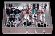
Well, I finally got around to completing this project, or so I thought.
While I had only 1 set of inputs and one set of outputs wired, everything was perfect. I wired in the extra output (I already had the Balanced output wired, and added the single ended outpout) everything was still fine.
Next I wired in all the inputs. Before I had one balanced input and one single ended inpout wired, and everything was fine. I now added another balanced input and three more single ended inputs. Now, when I select a single-ended input that is connected to a source (whether or not the source is turned on), I get a low level ground loop hum.
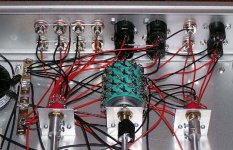
For reference, I am posting a rough layout of how I have everything connected. My overall goal with the connection schemem was to avoid needing to jumper the negative and ground XLR pins when using a single ended source or amp, and I am trying to achieve it through the switching arrangement.
I tried inserting an 8 ohm resistor between the RCA connections and the star ground to break the loop, but that just made the hum much much worse. So now I am thinking that I need to break the connections between the individual RCS connector grounds?
Wouldn't mind a little feedback on the issue from those who know better.
Cheers, Terry
While I had only 1 set of inputs and one set of outputs wired, everything was perfect. I wired in the extra output (I already had the Balanced output wired, and added the single ended outpout) everything was still fine.
Next I wired in all the inputs. Before I had one balanced input and one single ended inpout wired, and everything was fine. I now added another balanced input and three more single ended inputs. Now, when I select a single-ended input that is connected to a source (whether or not the source is turned on), I get a low level ground loop hum.
For reference, I am posting a rough layout of how I have everything connected. My overall goal with the connection schemem was to avoid needing to jumper the negative and ground XLR pins when using a single ended source or amp, and I am trying to achieve it through the switching arrangement.
I tried inserting an 8 ohm resistor between the RCA connections and the star ground to break the loop, but that just made the hum much much worse. So now I am thinking that I need to break the connections between the individual RCS connector grounds?
Wouldn't mind a little feedback on the issue from those who know better.
Cheers, Terry
Attachments
Is the GND from power supply connected to housing (AC GND)?
In my experience, the audio circuit (incl. PSU) should be only 1x connected to housing. I had a similar problem with my AP1.7.
I connected GND-left with GND-right direct at PSU and with a short wire with housing -> ghostly quiet. XLR and RCA are all insulated mounted.
Maybe it helps.
Regards
Adam
In my experience, the audio circuit (incl. PSU) should be only 1x connected to housing. I had a similar problem with my AP1.7.
I connected GND-left with GND-right direct at PSU and with a short wire with housing -> ghostly quiet. XLR and RCA are all insulated mounted.
Maybe it helps.
Regards
Adam
Originally posted by acaudio
Is the GND from power supply connected to housing (AC GND)?
In my experience, the audio circuit (incl. PSU) should be only 1x connected to housing. I had a similar problem with my AP1.7.
I connected GND-left with GND-right direct at PSU and with a short wire with housing -> ghostly quiet. XLR and RCA are all insulated mounted.
Thanks Adam,
The power supply is dual mono after the trafo's, and the L and R PS GND's are connected to the L and R Star Grounds. Each Star Ground is connected directly to the AC GND via a CL-60 thermistor, a la Mr. Pass. The chassis is connected directly to the AC GND, but the RCA jacks are all isolated from the chassis. I find it very interesting that the balanced inputs do not show the same behaviour!
Any and all thoughts are welcome.
Terry
Originally posted by pinkmouse
Can you trace the hum to just one piece of kit by unpluging them one at a time?
I tried that, and even when only one single eneded source is connected, I get the hum. I also tried connecting the same source to each of the SE inputs, and the hum followed. The hum when my cd player is selected is pretty low in level, and I can almost pretend it isn't there, but when I use my TV as a source the hum is too high to be ignored.
- Status
- Not open for further replies.
- Home
- Amplifiers
- Pass Labs
- CC-CCS-X-BZLS: It's alive!