I found even more problems, the alligator clips I used weren't designed for high currents... each clip was about 0.5 ohms and I used a lot of them.
I swapped wires on all of them and re-did my original measurements with a fixed filter. Now it is a bit more efficient too which is nice.
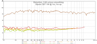
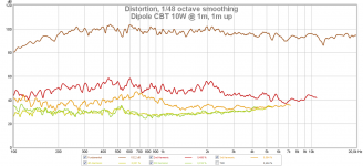
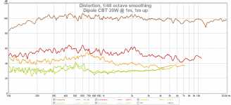
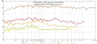
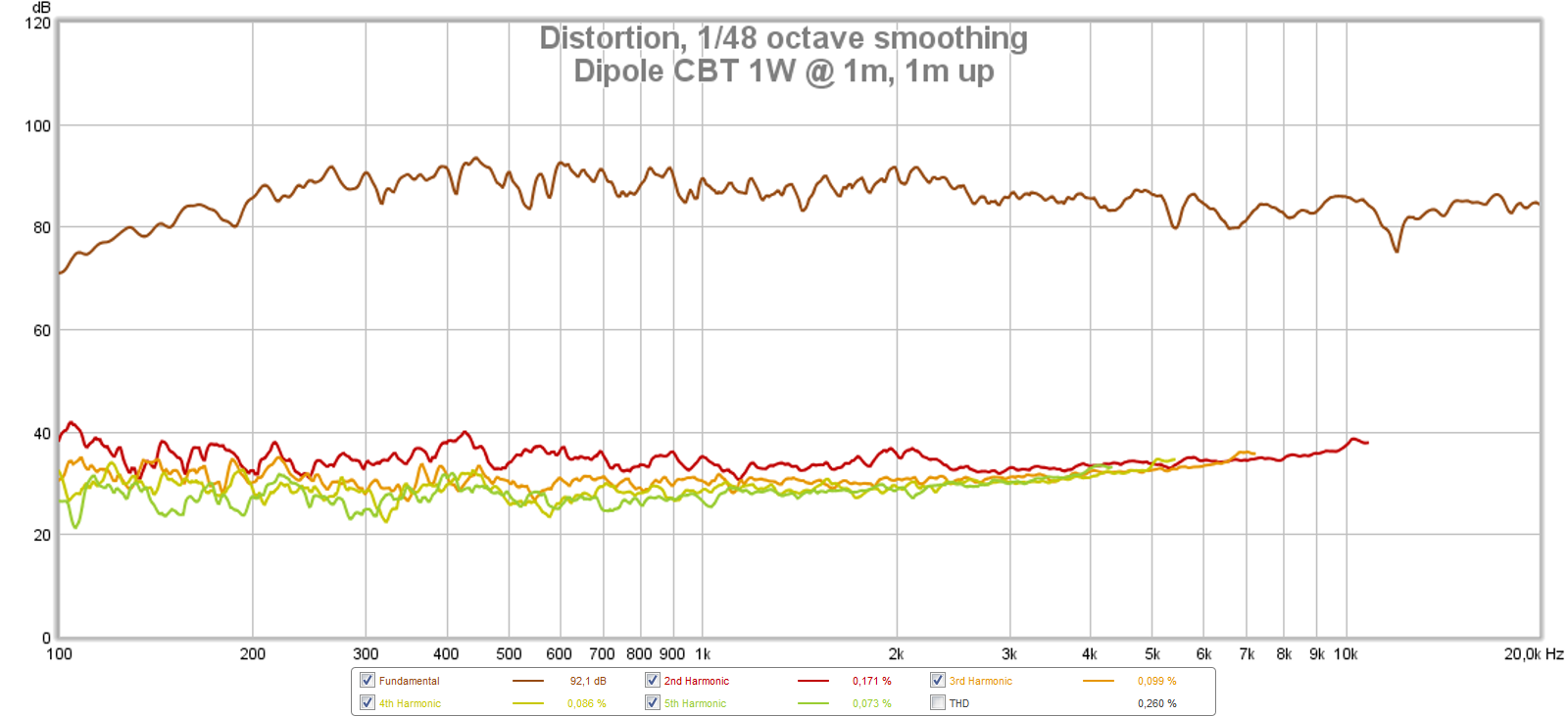
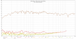
The 1W efficiency is 89 dB falling of 1.5 dB / octave from about 800 hz. And it can definently play loud enough, at 40W it hits 106 dB @ 1m out from bottom, 1m up. And even here there is no sharp increase in distortion which is nice.
It measures even more smooth in the room too, which is also nice.
I did test a not ground plane setup where I flipped the array 35 degrees. It worked, perhaps too well. The vertical directivity was a bit too small so just by sitting and standing the loudness differed by 4 dB at 1m distance. If I want to test non groundplane designs further I'll have to use the curve as the non ground plane one, 70 degrees. I can't bodge such a test with the current enclosure though.
I swapped wires on all of them and re-did my original measurements with a fixed filter. Now it is a bit more efficient too which is nice.
The 1W efficiency is 89 dB falling of 1.5 dB / octave from about 800 hz. And it can definently play loud enough, at 40W it hits 106 dB @ 1m out from bottom, 1m up. And even here there is no sharp increase in distortion which is nice.
It measures even more smooth in the room too, which is also nice.
I did test a not ground plane setup where I flipped the array 35 degrees. It worked, perhaps too well. The vertical directivity was a bit too small so just by sitting and standing the loudness differed by 4 dB at 1m distance. If I want to test non groundplane designs further I'll have to use the curve as the non ground plane one, 70 degrees. I can't bodge such a test with the current enclosure though.
Attachments
Congratulations! Super result and very nice execution. Awesome project!

Very nice frequency response - super neutral and natural sounding I bet.
Very nice frequency response - super neutral and natural sounding I bet.
I got a crazy idea I might build a crude prototype of to test further:
As I mentioned earlier in the thread I did build a prototype non ground plane 70 degree frame but I discarded it as due to looks, it was not pretty. It bulged forward and looked a lot bigger than the ground plane one even if they were the same height and had the same amount of drivers.
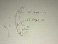
If I use a more gentle curve, the visual pollution isn't as much of a problem and I've tested that with a 35 degree arc. It, however, didn't measure as well as I wanted since the vertical sweet spot was minimal. But then I got one of my crazy ideas:
Why not do both? Why not do an assymetric design where I use a 70 degree arc on the top where since it slopes backwards it looks pretty nice and a more gentle arc, say 35 degrees on the bottom? It would also have the benefit of less output to the floor which would reduce floor bouncing effects while having a wider vertical sweet spot above which is what I want.
And also, I think it would look really cool 😎
As I mentioned earlier in the thread I did build a prototype non ground plane 70 degree frame but I discarded it as due to looks, it was not pretty. It bulged forward and looked a lot bigger than the ground plane one even if they were the same height and had the same amount of drivers.
If I use a more gentle curve, the visual pollution isn't as much of a problem and I've tested that with a 35 degree arc. It, however, didn't measure as well as I wanted since the vertical sweet spot was minimal. But then I got one of my crazy ideas:
Why not do both? Why not do an assymetric design where I use a 70 degree arc on the top where since it slopes backwards it looks pretty nice and a more gentle arc, say 35 degrees on the bottom? It would also have the benefit of less output to the floor which would reduce floor bouncing effects while having a wider vertical sweet spot above which is what I want.
And also, I think it would look really cool 😎
Attachments
Last edited:
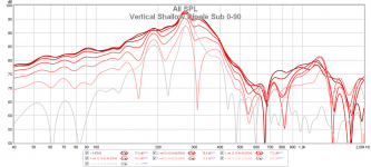
It'd be nice to see the graphs at 5dB increments, instead of a masking 20dB.
Ask and you shall recieve =)
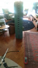
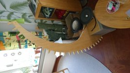
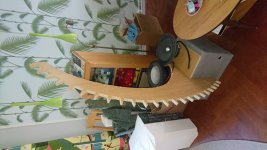
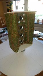
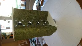
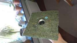
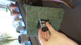
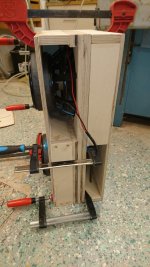
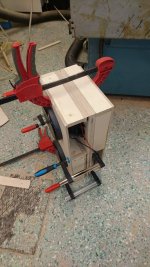
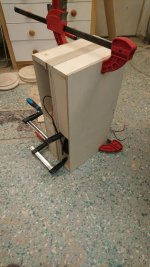
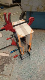
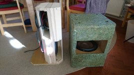
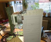
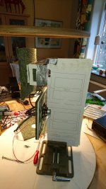
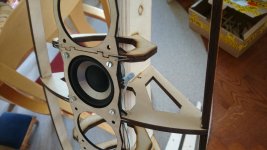
I also got some work done on my next prototype: It is a bit front heavy so the woofers are there as weights. The gray pouffe in the pictre is a W-frame sub.
I think it looks rather nice. I'll have to wait until next weekend (or maybe friday) to mount drivers and do some test measurements.
Attachments
I re-did the test where I added baffle width to the array and reconfigured it to be +- 35 degrees and compare the sensitivity to + 70 degrees. My train of thought was: with the 0-point at 80 cm height rather than the floor, I should have higher sensitivity.
The result was... no. I didn't even bother to save the meassurement (I forgot) but it was pretty much identical to the ground plane configuration. Within my margin of error when measuring at least.
So I'm back to ground plane =)
One thing that did raise the sensitivity by 1.5 dB was to increase the baffle width to 30 cm all the way to the top (The distortion measurements have this). And since I did that calculation error the baffle width on the top is too short I might as well re-do and make it better.
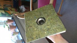
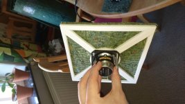
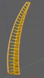
And when I'm at it I want to keep a higher efficiency but still not have a too wide speaker, so I have started to prototype folding the baffle:
The configurations are:
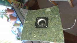
1. Wool sheet on the front
2. Wool sheet on the back
3. Foamcore ribs + wool sheet on the front
4. Foamcore H-frame-ish frame with wool. I should have taken pictures before the wool but I have used my paint skills to show the ribs beneth, kinda like 3. but with triangles to hold up the wool sheet. The rest of the waveguide is just hollow.
Measurements in next post:
The result was... no. I didn't even bother to save the meassurement (I forgot) but it was pretty much identical to the ground plane configuration. Within my margin of error when measuring at least.
So I'm back to ground plane =)
One thing that did raise the sensitivity by 1.5 dB was to increase the baffle width to 30 cm all the way to the top (The distortion measurements have this). And since I did that calculation error the baffle width on the top is too short I might as well re-do and make it better.
And when I'm at it I want to keep a higher efficiency but still not have a too wide speaker, so I have started to prototype folding the baffle:
The configurations are:
1. Wool sheet on the front
2. Wool sheet on the back
3. Foamcore ribs + wool sheet on the front
4. Foamcore H-frame-ish frame with wool. I should have taken pictures before the wool but I have used my paint skills to show the ribs beneth, kinda like 3. but with triangles to hold up the wool sheet. The rest of the waveguide is just hollow.
Measurements in next post:
Attachments
-
 4.Xbaffle_wireframe.jpg315.5 KB · Views: 208
 -
 4.Xbaffle_front.jpg706.9 KB · Views: 196
 -
 4.Xbaffle_back.jpg706 KB · Views: 172
 -
 3.FoamcoreBaffleFront_front.jpg914.1 KB · Views: 179
 -
 3.FoamcoreBaffleFront_back.jpg758.2 KB · Views: 193
 -
 2.WoolBack_front.jpg981.2 KB · Views: 171
 -
 2.WoolBack_back.jpg819 KB · Views: 165
 -
 1.WoolFront_front.jpg740.3 KB · Views: 248
 -
 1.WoolFront_back.jpg857.3 KB · Views: 248
With 1-3 I wanted to test if I get best results with wool sheet on the front or back of driver. And in case of 3 if I can have a small baffle that I attach the driver to and then glue the wool to this baffle for a more easy build.
With 4 I wanted to see if I get worse performance by incerasing baffle width by a lot and folding it. The baffle is 20 cm wide and 15 deep so should be comparable to ~ 40 cm diameter if my calculations are correct. On my flat prototype the bottom width is 30 cm so this setup would yield a lot wider baffle => more efficiency for the same size.
All in all the folded baffle seems to perform great, next step is to scale it up. I'll probably continue investigating putting the wool sheet on the front as it measures slightly better. Just have to figure out how I can make the construction first =)
I forgot to mention, no shading has been added in 4. Probably explains the 14k dip.
Attachments
-
 4. SB65 X frame 90-180.png271.9 KB · Views: 121
 -
 4. SB65 X frame 0-90.png258.2 KB · Views: 122
 -
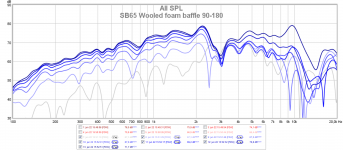 3. SB65 Wooled foam baffle 90-180.png281 KB · Views: 126
 -
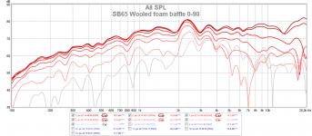 3. SB65 Wooled foam baffle 0-90.png255 KB · Views: 117
 -
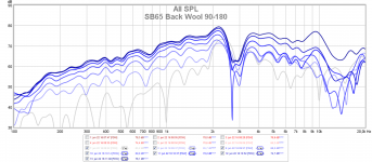 2. SB65 Back Wool 90-180.png272.7 KB · Views: 140
 -
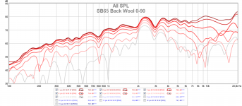 2. SB65 Back Wool 0-90.png260.9 KB · Views: 141
 -
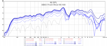 1. SB65 Front Wool 90-180.png257.2 KB · Views: 150
 -
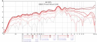 1. SB65 Front Wool 0-90.png256.4 KB · Views: 201
Last edited:
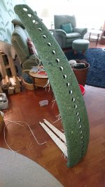
Some slow progress, but progress nonetheless!
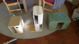
As I showed in post #14 (CBT Dipole with SB65WBAC25-4) the rear sub I currently have is a bit too wide for my liking. I'm experimenting with putting the drivers on top of each other to reduce width.
It is almost ready for measurements, I want to make it even smaller though: I'm planning on cutting a 45 degree chamfer on the outer edges to make it look smaller. It should also push the W-frame resonance up higher in frequency which is nice considering I would like to cross at 140-170 hz.
Attachments
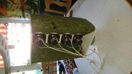
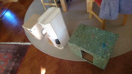
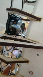
Some more progress pics:
The base is temporary, the current plan is an oak base that will probably be a bit wider in the non-magnet direction. The actual sub will also be covered in wool + fabric.
I havent measured it yet but I have a good gut feeling. Based on distance from front to back I expect it to have very slightly less low frequency output than the big W-frame but nothing worth worrying about. It should have less of a resonance though which will let me cross higher without issues which fits the full range drivers much better.
It is a lot less visually polluting too which I really like.
Attachments

Although it does vibrate a lot more than the W-frame which makes sense. I'll probably test build a symmetrical push-push (like a ripole) with minimized width and chamfered edges too and see how that looks and performs.
I saw that you calculated Cosine shading. Do you happen to know how to calculate Chebychev shading? It would be nice if a math genius created a spreadsheet to calc the various shading networks. At least if it can be done in a spreadsheet. I don't know enough to know if it's a job for MathCad instead.
I saw that you calculated Cosine shading. Do you happen to know how to calculate Chebychev shading? It would be nice if a math genius created a spreadsheet to calc the various shading networks. At least if it can be done in a spreadsheet. I don't know enough to know if it's a job for MathCad instead.
No idea about the Chebychev, only tested Cosine and Lagrange in a semi-ugly spreadsheet I wrote: CBT shading - Google Sheets
EDIT: Seems the shading function dropdown is not pluggable in read-only mode :'(
The Lagrange function used is the one from Keeles introduction PDF: https://www.linkwitzlab.com/Keele - Introduction to CBT Loudspeaker Arrays.pdf
See slide 44, "Power Series Approximation of Legendre
Shading Function"
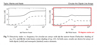
Went further with Cosine though because of this paper: https://www.keele-omholt-technologi...ty-Circular-Arc-Arrays-of-Dipole-Elements.pdf
More specifically Fig7 which shows that with a wide beam Cosine shading & a dipole the directivity above and below the CBT transition point is pretty much the same. That of course is is very nice when transitioning to pure dipole radiation in the lower frequencies with subs.
Last edited:
What was your thought process behind choosing a 70 degree arc? I built mine in a straight format using time delay so I could adjust the arc angle. In casual listening I don't notice a difference between a narrow or wide arc on my larger CBTs but I *think* I notice a difference on the smaller 29 inch CBT column. I haven't measured the vertical field yet on the smaller column to confirm what I think my ears are hearing.
What was your thought process behind choosing a 70 degree arc? I built mine in a straight format using time delay so I could adjust the arc angle. In casual listening I don't notice a difference between a narrow or wide arc on my larger CBTs but I *think* I notice a difference on the smaller 29 inch CBT column. I haven't measured the vertical field yet on the smaller column to confirm what I think my ears are hearing.
For the same reason Keele used a 70 degree cosine arc as shown in the image stolen from https://www.keele-omholt-technologi...ty-Circular-Arc-Arrays-of-Dipole-Elements.pdf Fig7.
The 70 degree wide beam cosine shaded arc has a constant directivity even when you go below the cutoff of the CBT due to the size of the array. Because my goal is constant directivity over the whole frequency range that is something I want as they will integrate perfectly with my subs.
And I have thought about building a straight time delayed version too but there are several reasons I went with physical curve:
- In Keeles introduction PDF, he shows that in theory the physically curved array measures better. It should also have less high frequency beaming since the drivers have less directivity in the high frequency region thus fewer drivers actually combine and interfere with each other.
- It would be a lot more complex. At the moment I have 6 analogue channels with DSP, I'd have to buy a lot more DSP channels and have a lot more amplifiers. Ideally I'd need one channel for each driver which is a lot.
- Aesthetics: I like the look of the curve. It curves away from the listener too so present a smaller silhouette.
Attachments
Last edited:
I've done some toe dipping in planars to see if going 2-way with planar midtweeters would improve things. Turns out it didn't so I'm back 😀
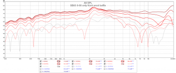
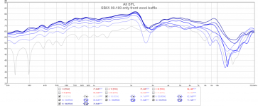
I've been trying out more baffle geometry and also testing a passive cardioid design. It's an interesting idea so worth pursuing. I threw together a prototype by copying the design from other projects with leaky cardioid mids. It measured far better rear wave suppression than I expected. I especially didn't expect that the response would improve that much by adding an extra wool baffle to the front.
But while it does measure amazing on the polars there is just something wrong with it. I setup and EQed both of them to flat response identical to each other and then A/B switched and listened. There is just something wrong with the cardioid version. The more I think about it my guess is that the dipole magic might not be the dipole pattern but rather the lack of box coloration. there is definently a box sound, a coloration / resonance of some sort in the leaky cardioid. When listening to midbass instruments like a tuba / cello it sounds like there is a muffler or something on the sound. An echo or something where the pure dipole doesn't have this problem and sounds more pure.
It might be possible to build a better cardioid but I don't think I will investigate it further as of now. I know Linkwitz used a long transmission line in the Pluto but I'm not sure how I would practically build such a setup in a physically curved CBT. And on top of that it would be absolutely HUGE.
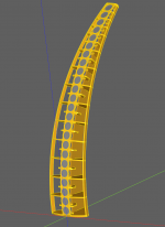
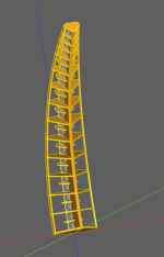
So as a sneak peek I have CAD drawings of the next CBT iteration which will most likely be another pure SB65 array. But one where I mount the drivers to the rear of the wood baffle instead of from the front. This is to block less of the rear wave of the driver since the space on the rear is pretty tight. The whole front will of course have a wool sheet like in my other experiments to improve efficiency.
I've been trying out more baffle geometry and also testing a passive cardioid design. It's an interesting idea so worth pursuing. I threw together a prototype by copying the design from other projects with leaky cardioid mids. It measured far better rear wave suppression than I expected. I especially didn't expect that the response would improve that much by adding an extra wool baffle to the front.
But while it does measure amazing on the polars there is just something wrong with it. I setup and EQed both of them to flat response identical to each other and then A/B switched and listened. There is just something wrong with the cardioid version. The more I think about it my guess is that the dipole magic might not be the dipole pattern but rather the lack of box coloration. there is definently a box sound, a coloration / resonance of some sort in the leaky cardioid. When listening to midbass instruments like a tuba / cello it sounds like there is a muffler or something on the sound. An echo or something where the pure dipole doesn't have this problem and sounds more pure.
It might be possible to build a better cardioid but I don't think I will investigate it further as of now. I know Linkwitz used a long transmission line in the Pluto but I'm not sure how I would practically build such a setup in a physically curved CBT. And on top of that it would be absolutely HUGE.
So as a sneak peek I have CAD drawings of the next CBT iteration which will most likely be another pure SB65 array. But one where I mount the drivers to the rear of the wood baffle instead of from the front. This is to block less of the rear wave of the driver since the space on the rear is pretty tight. The whole front will of course have a wool sheet like in my other experiments to improve efficiency.
Attachments
-
 DSC_0742.jpg308.9 KB · Views: 349
 -
 DSC_0746.JPG491.5 KB · Views: 355
 -
 DSC_0749.jpg367.9 KB · Views: 353
 -
 SB65 0-90 only front wool baffle.png118.3 KB · Views: 348
 -
 SB65 90-180 only front wool baffle.png115.9 KB · Views: 166
 -
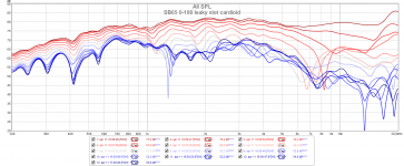 SB65 0-180 leaky slot cardioid.png178.5 KB · Views: 141
 -
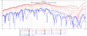 SB65 0-180 leaky slot cardioid with wool baffle.png231.3 KB · Views: 153
 -
 fr-1.png132.3 KB · Views: 186
 -
 fr-2.png124.9 KB · Views: 169
 -
 fr-3.png134.4 KB · Views: 171
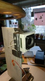
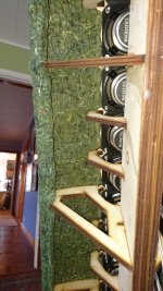
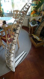
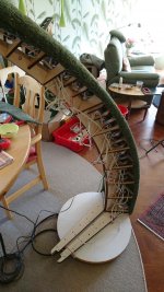
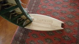
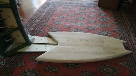
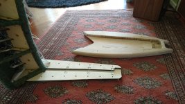
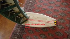
Progress!
The base is not completed. What you see is the inner bits. There will be an outer oak base. The inner plywood parts are such that I can easily route the cables inside the base with the binding posts at the rear of the base =)
I will add some more wool carpet to the edge and the rear spine. And then lastly it will all be covered up in fabric. I'm leaning towards using thin linen since I like the structured look of it.
No measurements yet but I'm hopeful, next weekend I will be able to get some measurements.
Attachments

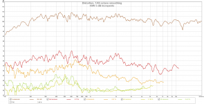
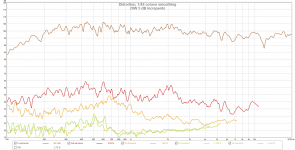
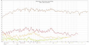
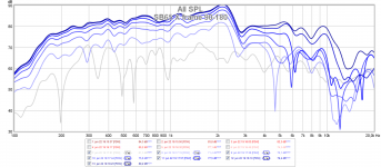
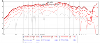
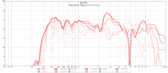
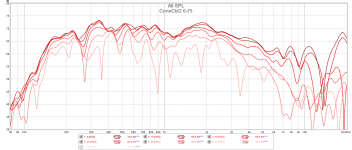
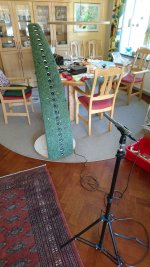
Preliminary measurements!
It is a simplified shading network. The 5 uppermost drivers have identical shading, and so does the next 4 uppermost after that. In the final shading network I'll shade each of those drivers individually but It was easy to connect for now so that is what I went with.
Since my planar experiment didn't measure well I wanted to confirm that the new design works well before I start finalizing the design with fancy wood and building the fabric cover.
The measurement is with with no EQ apart from a 140 hz LR2 highpass. I threw in the 8" planar experiment measurements as a comparison. The SB65 FR design performs a lot better than the planar version. It measures as good as I hoped it would.
So now I just have to finish them 😀
Attachments
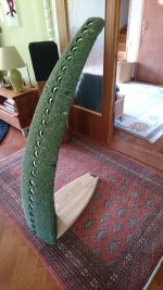
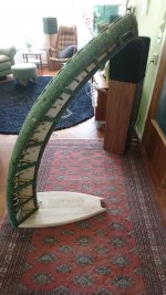
Some progress on the base.
TODO is:
TODO is:
- Add binding posts at the rear of the base while routing the cables inside the base.
- Stain the wood and apply hardwax oil finish
- Solder the shading network, I have a stack of PCBs to help.
- Sew the fabric cover.
- Done =)
Attachments
Looking real nice there 🙂
I wanted to ask you if you got a good deal on bulk amounts of the SB65, and from where in that case? I'm planning a smaller 2-way line-source and want to use the correct drivers already in the prototypes to get real world measurements before committing to making the cabs....
I wanted to ask you if you got a good deal on bulk amounts of the SB65, and from where in that case? I'm planning a smaller 2-way line-source and want to use the correct drivers already in the prototypes to get real world measurements before committing to making the cabs....
- Home
- Loudspeakers
- Full Range
- CBT Dipole with SB65WBAC25-4