That's what I get for copying and pasting.Wow!
A 10uF driving a 1 Meg Ohm resistor.
R x C Time constant is 10 seconds.
The time constant to settle to final DC voltage is 50 seconds.
Still, the DC voltage on the tube side of the cap will only be about 5V.
Plan a Mono or Stereo System, that is put together by connecting many individual components . . .
In order to get an idea of how well a complete system might perform, it is very helpful to find full specifications, or measure the specifications of inputs and outputs (measuring is more easily said than done).
Electronics:
Phono preamps, preamps, power amps.
Inputs: Voltage drive that is needed, input impedance (at least know the DC resistance, it is also helpful to know the input capacitance too). Gain.
Outputs: Output Voltage, output impedance; Gain; Output Power, Output tap ratings (nominal tap rating like 4, 8; damping factor).
Phono cartridges: Voltage out; required load impedance (minimum / maximum)
CD players, Tuners, TV audio out, etc.: Voltage out, load impedance minimum
RCA phono cables: capacitance
Loudspeakers: Nominal and minimum impedance; Efficiency dB at 1 Watt at 1 Meter.
Room Size and treatment: Will it swallow up most of the sound or not?
Without proper planning, the system may not perform to your liking.
With proper planning, the system may, or may not, perform to your liking.
Or, just put lots of products together, they might be synergistic, and to your liking (if so, go and gamble, your luck is on the rise).
We are at Post # 42, and have not arrived at a planned system.
Last edited:
aria,
I read through all the posts again.
Looking at Post # 1, questions I forgot to ask are:
What were the loudspeakers that were used on that amplifier in post #1?
That might be part of why you were so impressed with the sound of that system.
It most likely was not a loudspeaker with only 82dB/1Watt/Meter sensitivity.
And the loudspeaker minimum impedance was probably not as low as 2 Ohms.
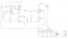
You said 'the preamp was roughly" the right schematic.
Was the complete amp including power amp the left schematic, roughly the amplifier that was used?
Or is that schematic a composite amp or another amp design?
System is the key word.
I read through all the posts again.
Looking at Post # 1, questions I forgot to ask are:
What were the loudspeakers that were used on that amplifier in post #1?
That might be part of why you were so impressed with the sound of that system.
It most likely was not a loudspeaker with only 82dB/1Watt/Meter sensitivity.
And the loudspeaker minimum impedance was probably not as low as 2 Ohms.
You said 'the preamp was roughly" the right schematic.
Was the complete amp including power amp the left schematic, roughly the amplifier that was used?
Or is that schematic a composite amp or another amp design?
System is the key word.
Last edited:
aria,
I read through all the posts again.
Looking at Post # 1, questions I forgot to ask are:
What were the loudspeakers that were used on that amplifier in post #1?
That might be part of why you were so impressed with the sound of that system.
It most likely was not a loudspeaker with only 82dB/1Watt/Meter sensitivity.
And the loudspeaker minimum impedance was probably not as low as 2 Ohms.
You said 'the preamp was roughly" the right schematic.
Was the complete amp including power amp the left schematic, roughly the amplifier that was used?
Or is that schematic a composite amp or another amp design?
System is the key word.
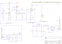
There is a lot of confusion on this post, my fault...
On post 1 there is a sketch of an amplifier with CF that never took off + the schematics of a preamp that I listened to some time ago and which is also present on the net with schematics and legendary explanation (in Italian):
T-Project 1: Preamplificatore a Valvole "Meeting"
After some time I used the same post to question a completely different project that had the use of CF as the only glue. The desire was to think of a very low cost system that sounded good (not high-end necessarily)...
the posistive features of that project which make it accessible to all budgets while maintaining a decent quality are:
1) Using a sub by splitting the signal means being able to have double the power and being able to use a usual medium sensibilty loudspeakers only for the mid-high freq...
2) Using it means being able to use a couple of good old OT found in old radios ... the only discriminating factor is the presence of a 6 ohm secondary winding in order to have an adequate Z Ratio to use EL84s (or any other 5k load tube that has a good response even at 7k) with a pair of usual 8 ohm loudspekers (Philips and other old brands made them)...
3) Using it you can employ few tubes, even inexpensive ones.
4) Using it you don't need a lot of space to build it.
Last edited:
aria,
I read through all the posts again.
Looking at Post # 1, questions I forgot to ask are:
What were the loudspeakers that were used on that amplifier in post #1?
That might be part of why you were so impressed with the sound of that system.
It most likely was not a loudspeaker with only 82dB/1Watt/Meter sensitivity.
And the loudspeaker minimum impedance was probably not as low as 2 Ohms.
You said 'the preamp was roughly" the right schematic.
Was the complete amp including power amp the left schematic, roughly the amplifier that was used?
Or is that schematic a composite amp or another amp design?
System is the key word.
They were components that I knew well, some I had even had at home ... we also tested it with both solid state and tubes ...
Oh the poor 12ax7 being called wimpy again. It has its place but not here.
For lower z but less gain use 12AU7.
I find its not so touchy as 12AX7.
a cathode follower is a topology that doesn't provide "colour" to the sound.
Given same current goes through cathode as anode any colour on the anode will be on cathode too. I would have thought ?
poor 12ax7, poor 12au7 we talking for the 85% of the preampl. out there. the audio
tube industry are laughing with these coments
tube industry are laughing with these coments
poor 12ax7, poor 12au7 we talking for the 85% of the preampl. out there. the audio
tube industry are laughing with these coments
To get to 85% you have to add ECC88 ... I have been wondering for a while if this is more due to the lack of imagination of the designers or the interests of the tube industries in pushing only a few tubes ... purchase prices and the proliferation of late bad quality tubes sold at higher prices than excellent NOS tubes that have only the defect of being less known...not to mention their NOS counterparts which thus also reached 2 zeros!... this was one of the reasons that prompted me to try to understand something more about them and their use...
Last edited:
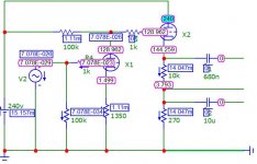
If the line below the 01 out is intended for output it should contain a second cap. Or does the line have another meaning?
If the line below the 01 out is intended for output it should contain a second cap. Or does the line have another meaning?
the first exit from the top is for the power tube, the second for amplified sub.

Here a small video of the amplifier.
But I need to ask you for some advice: since the preamp is inverting, how can I do to restore the right phase?
EL84 plate impedance is around 40,000 ohms wired as a pentode (at the book operating point at least). To get useful output for HiFi, you can use a 120,000 ohm output transformer (impossible) or throw some feedback around the circuit. A more reasonable option would be to just triode strap the EL84.
You will get more power when triode strapping because the distortion will drop so substantially.
There is also no reason (once you have tamed the gain/THD/damping issues) that you can't take your subwoofer output off the speaker taps.
You will get more power when triode strapping because the distortion will drop so substantially.
There is also no reason (once you have tamed the gain/THD/damping issues) that you can't take your subwoofer output off the speaker taps.
For those who have a single ended Ultra Linear output stage, they do not want to reverse the connections of B+ and Plate connections of the primary.
Well . . . Why not try it?
Example:
A 43 % UL Tap will become a 57 % UL tap (changing it closer toward triode mode).
26% changing to 74%, anybody?
Have fun modifying and listening!
Just Saying
Well . . . Why not try it?
Example:
A 43 % UL Tap will become a 57 % UL tap (changing it closer toward triode mode).
26% changing to 74%, anybody?
Have fun modifying and listening!
Just Saying
- Home
- Amplifiers
- Tubes / Valves
- Cathode Follower, again