No, I would like to build something similar to the amplifier which is on the left. I would also like to compare it, with the same wattage with the pentode version with a single tube that I already built. I took as an excuse the scheme of that pre to try to imagine it inside the amplifier. Reading the explanations of the person who designed it, I persuaded myself that it could be a good solution also in the future perspective of other projects.
As for EC86: it has a lower commercial value than the 6DJ8 standard and, with the same construction quality (for example with an E88CC SE), a price 10 times lower.
Thought you wanted a driver stage for the 6Y6 amplifier stage, thats why I said it was a waste of heat, what you want is an overkill preamplifier, then yes you can use a 6as7, 6s19p as output, or what ever you want because you don't know the impedance of the amplifier you are going to connect it to, but then advise has been given a 6n1p, 6sn7, 6cg7, ecc88, or any variant of those, will have a good low output impedance even for solid amplifiers we are talking about those tubes able to drive ~10k loads with ease, a 6as7 variant like the one you want to use will go even lower, but it wont be any easy to get low noise from them them cause they use lots of current and that can get a nasty hum in the audio when a poor layout is implemented.
Yes, that is a good choice.
And i like the tube, like 7247 / 12dw7 but other spec.
They are stunning tubes... they are suitable for CF, but also for a complete triode amplifier with a single tube, able to give up to 1.2w approx.
Thought you wanted a driver stage for the 6Y6 amplifier stage, thats why I said it was a waste of heat, what you want is an overkill preamplifier, then yes you can use a 6as7, 6s19p as output, or what ever you want because you don't know the impedance of the amplifier you are going to connect it to, but then advise has been given a 6n1p, 6sn7, 6cg7, ecc88, or any variant of those, will have a good low output impedance even for solid amplifiers we are talking about those tubes able to drive ~10k loads with ease, a 6as7 variant like the one you want to use will go even lower, but it wont be any easy to get low noise from them them cause they use lots of current and that can get a nasty hum in the audio when a poor layout is implemented.
the pre designer provided it with low output impedance and good current reserves because a pre never knows what will drive first and it must be ready for all loading needs.
if the driver stage for 6Y6 does not need this it is useless, and as you say, deleterious to use 6AS7 or similar.
for a purely aesthetic question I would like to use 6GF7A to make an "all nude" tubes amplifier.

Looks good the follower is done with the stronger triode of the 6EM7 it will have the guts certainly
Looks good the follower is done with the stronger triode of the 6EM7 it will have the guts certainly
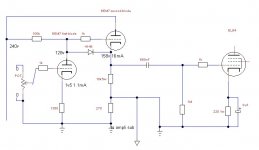
I always use 6EM7 simply because I only have those in a good quantity and that can do that job decently with a single tube ... actually I'd like to understand if, in that configuration, it can drive a powered subwoofer that usually asks for 4v and 1k5 ohm impedence approx. + a pair of EL84 (for example)... and if it makes sense to put low pass and high pass filter after CF
The filter itself will cause a complex impedance you can model it and including the output load, or you can make it high enough to don't cause trouble as a load seen by the tube follower.... But the response will be very sensible to the load and will be severely attenuated or you can use another bottle and make another follower so you can have similar levels in both outputs without the inconvenience of the lower output at the sub input, perhaps a better solution would be using opamps smaller overall profile and lower overall noise. Using amplifiers with very different impedance calls for a trouble not counting the sensibility needed for both when using a common input.
Do you think something like this could work well?
Only if you're comfortable with a 158v DC offset into your subwoofer amp. 😱

Please don't do that - you need a coupling capacitor and a DC ground reference resistor on that output as well.
Last edited:
Doing some napkin maths a 6em7 cathode follower will have a output impedance of ~150 ohms it will drive the sub output nicely, now is your turn to design a proper filter that accounts for the task 😀
Sorry didnt see the missing capacitor but I think the op is fully aware it need to be AC coupled, 150V DC offset will cause fireworks at the sub amplifier. 😛
Sorry didnt see the missing capacitor but I think the op is fully aware it need to be AC coupled, 150V DC offset will cause fireworks at the sub amplifier. 😛
I bet the sub plate amp has a cap at the input, but I also bet that having an RCA cable with 150V on the center pin would make for some unanticipated excitement!
Why the LPF when the sub should have one built in? You're also making a metric ton of gain before feeding the sub amp, why not put a little resistance between the 10K and ground and take your sub output from there?
Why the LPF when the sub should have one built in? You're also making a metric ton of gain before feeding the sub amp, why not put a little resistance between the 10K and ground and take your sub output from there?
The filter itself will cause a complex impedance you can model it and including the output load, or you can make it high enough to don't cause trouble as a load seen by the tube follower.... But the response will be very sensible to the load and will be severely attenuated or you can use another bottle and make another follower so you can have similar levels in both outputs without the inconvenience of the lower output at the sub input, perhaps a better solution would be using opamps smaller overall profile and lower overall noise. Using amplifiers with very different impedance calls for a trouble not counting the sensibility needed for both when using a common input.
you are right, it is much more complicated than how they presented it to me ... in addition to all the problems you exposed there is also the low pass filter inside the sub to consider ... it would be certainly easier to separate the two stages and make each one to measure ... in theory the high pass filter already makes it the small OT and the low pass filter the sub (because the basic idea was to remedy the lack of low frequencies on a small OT with the help of a sub).
Last edited:
I bet the sub plate amp has a cap at the input, but I also bet that having an RCA cable with 150V on the center pin would make for some unanticipated excitement!
Why the LPF when the sub should have one built in? You're also making a metric ton of gain before feeding the sub amp, why not put a little resistance between the 10K and ground and take your sub output from there?
making a voltage divider?
Doing some napkin maths a 6em7 cathode follower will have a output impedance of ~150 ohms it will drive the sub output nicely, now is your turn to design a proper filter that accounts for the task 😀
Sorry didnt see the missing capacitor but I think the op is fully aware it need to be AC coupled, 150V DC offset will cause fireworks at the sub amplifier. 😛
to me it was an impedance of 1k4 ohm...
the sub output of my HT receiver has 4v and 1k5 ohm impedence, I relied on this.
Last edited:
For your experience, as a percentage, how much must be the positive balance between the voltage of the output signal from the preamplifier triode and the -Vg of the final tube?
Wow!
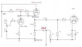
A 10uF driving a 1 Meg Ohm resistor.
R x C Time constant is 10 seconds.
The time constant to settle to final DC voltage is 50 seconds.
Be sure to use a low leakage plastic cap there.
An electrolytic cap might cause DC to appear at the subwoofer input.
10uF and 1 Meg Ohm is -3dB at 15.9 milli Hertz (0.0159 Hz).
(-1 dB at 31.8 milli Hertz; 0.0318 Hz)
What is the input resistance of your Subwoofer Amp?
That will determine the amount of capacitance needed, not the 1 Meg Ohm resistor.
You are driving the subwoofer out with a 270 Ohm resistor. Such a low impedance should be able to drive just about any input impedance at the subwoofer (and just about any length of shielded cable capacitance). This only needs to pass low frequencies.
Last edited:
Wow!
A 10uF driving a 1 Meg Ohm resistor.
R x C Time constant is 10 seconds.
The time constant to settle to final DC voltage is 50 seconds.
Be sure to use a low leakage plastic cap there.
An electrolytic cap might cause DC to appear at the subwoofer input.
10uF and 1 Meg Ohm is -3dB at 15.9 milli Hertz (0.0159 Hz).
(-1 dB at 31.8 milli Hertz; 0.0318 Hz)
What is the input resistance of your Subwoofer Amp?
That will determine the amount of capacitance needed, not the 1 Meg Ohm resistor.
You are driving the subwoofer out with a 270 Ohm resistor. Such a low impedance should be able to drive just about any input impedance at the subwoofer (and just about any length of shielded cable capacitance). This only needs to pass low frequencies.
I have no idea what the impedance is, I just know what the standard parameters of a sub output on HT receiver are ...
i only have 1 pair of polypropylene 10uF caps, but they only hold 250v .... do you have any alternatives?
Last edited:
- Home
- Amplifiers
- Tubes / Valves
- Cathode Follower, again