A few years ago, I did some measurements of ECC83 and ECC81 with and without degeneration in the cathode. I expected that, with a CCS load on the plate, the distortion and gain would be about the same. I was very surprised to see that the distortion was significantly higher with the cathode resistor unbypassed. I've moved twice since then and couldn't find my lab notebook with the setup and results documented, so given some recent discussion, I thought I'd just repeat the work.
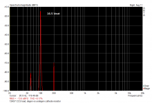
The circuit: a 12AX7 with a 0.8mA bipolar cascode CCS as a plate load, a 1k6 cathode resistor, and (for the undegenerated setup) a 470u bypass cap across the cathode resistor. The output was directly coupled to a source follower to minimize loading on the plate other than the CCS. 350V B+, 199V on the plate. GE 12AX7 (USA), so nothing exotic. 16.5V output.
To my surprise (and some relief), the distortion curves with and without the bypass cap overlaid perfectly. I repeated the setup and measurement several times to convince myself. Same result each time.
So, since I had a statement about distortion out there that was incorrect, I'm taking this opportunity to correct it. My earlier work was in error (don't know what), and the simple answer turns out to be the right one- the bypass is extraneous IF you have essentially an infinite plate load.
As a side note, look at that distortion spectrum: about -57dB, all second. And that's without optimizing the operating point, just plug and pray.
There's a diff amp in this tube's future...
Attachments
Glad to see it all worked out without violating any laws we took for granted 🙂 Thanks for checking and posting.
Edit: And on a related note, this would indicate LED bias is unnecessary with a stiff CCS.
Edit: And on a related note, this would indicate LED bias is unnecessary with a stiff CCS.
Last edited:
SY,
For a diff amp are you proposing a CCS load on each triode?
Have you tried a LTP with CCS tail and current mirror load (the way the SS guys like to do it)?
Cheers,
Ian
For a diff amp are you proposing a CCS load on each triode?
Have you tried a LTP with CCS tail and current mirror load (the way the SS guys like to do it)?
Cheers,
Ian
Impressive distortion spectra. Triodes really enjoy CCS loading.
And that's for 16V out - the distortion reduces with level. At 1.6V, it would be about 20dB lower.
Last edited:
Simplified thinking for new guys,
If you look at an equivalent circuit then you see a perfect (distortionless) voltage source whose output feeds a voltage divider consisting of tubes internal rp and the load impedance. The delta (change in) rp (with signal current swing) compared to the load impedance IS the distortion level (that is, it is the delta rp which is the distortion source).
To reduce distortion then you want to make that delta rp vs load impedance smaller by:
maximize the load impedance (CCS load)
minimise the delta rp by correct tube choice and operating point.
Note also that adding the CCS load minimizes the signal current swing (to achieve the same output voltage swing) and therefore also minimises the delta rp. A WIN WIN situation as far as distortion is concerned.
The CCS load gicves you double "bang for your buck".
Cheers,
Ian
Last edited:
Nothing special; cathode resistor is a feedback by current. It increases resulting output resistance, so it's variations on the same load impedance result in more distortions.
Edit: Ian already explained the math.
Edit: Ian already explained the math.
-57dB (0.14%) at 16Vrms is right in the middle of the spread I would expect for a 12AX7. Nice going!
An externally hosted image should be here but it was not working when we last tested it.
The nice thing is the spectrum- I was able to spot a little 3rd at -95dB by moving the scale around, but the second totally dominates. This is better performance than the 6SN7 which is a paragon of linearity. Of course, the plates MUST be buffered...
And Ian, yes, that is very much what I'm thinking for the diff amp. If you use a good CCS on the plates but a stiffer CCS in the cathode circuit, the circuit doesn't "fight" and can be brought into a stable balance.
And Ian, yes, that is very much what I'm thinking for the diff amp. If you use a good CCS on the plates but a stiffer CCS in the cathode circuit, the circuit doesn't "fight" and can be brought into a stable balance.
Although the increase in output resistance due to cathode degeneration is likely to be more linear than the original output resistance, as the increase depends on mu (roughly constant) while the original depends on both mu and gm (varies with current).Wavebourn said:It increases resulting output resistance, so it's variations on the same load impedance result in more distortions.
Is it possible that Stuart's original test was done with a faulty CCS, which had significantly nonlinear impedance? People often imagine that a CCS impedance is (nearly) infinite and (completely) linear. In the back of their minds they know that the 'infinite' is not really true but they can forget that the 'linear' is not really true either. At the high impedance levels seen at a 12AX7 anode (especially if degenerated) you need a very good CCS. Maybe instead of using CCS to measure 12AX7 distortion we should use 12AX7 to measure CCS distortion?
FWIW, the CCS I used earlier was the same bipolar cascode circuit. If I run across that notebook, I can review what my setup was exactly and look for potential error sources.
When you say "same circuit" do you mean literally the same physical piece of stuff, or something built using new components but from the same schematic?
Maybe I'm thinking about this too simply, but when one uses constant current sources in the anode, because the current is constant, doesn't that imply that the voltage drop on the cathode bias resistor is also constant, regardless of whether a bypass cap is employed, or not?
Which - if true (and I can't see how it wouldn't be true) - from the tube's perspective there is no cathode degeneration. But does this mean there is also no local NFB?
I think there is local NFB: with the CCS, this time from the phase-inverted plate-to-cathode swing. +100 mV in, -μ mV out. That's a lot of negative feedback to the operating point of the valve.
But it sure makes it easy to use a ruler with the old fashioned load-line calculator!
GoatGuy
I remember reading your results years ago and being really bothered (but trusting you). I feel better about the universe today. Thanks for the update.
When you say "same circuit" do you mean literally the same physical piece of stuff, or something built using new components but from the same schematic?
The CCS may have been the same one, the other components would not have been.
@ss, yeah, I was bothered as well, it didn't make any sense. But I always used LEDs anyway, so I didn't go back to it and dig in until the discussion about this last week. When I make a goof, I like to make 'em big.
- Status
- Not open for further replies.
- Home
- Amplifiers
- Tubes / Valves
- Cathode Degeneration with CCS plate load- My Mistake