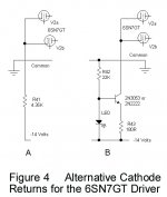
They’re K followers. Fixed bias on the grid at about -44V, which puts the Vg1 for the 6550s at what it needs to be for about 18 mA. Three per side, each is independently adjustable. The tails are at -200V through 16.5k resistors. Light loading on the previous triode stage, no re-biasing or blocking distortion even at low bias, and well inside the 50k ohm limit for 6550s with fixed bias. Won’t happen without that negative supply - but it’s just such a small addition to the overall cost.
That's an interesting approach, although it needs a fairly robust -200V supply to make it work. There is some similarity to the McIntosh MC60, but an extra stage of driver after the PI is required. I'm working with a fixed number of tubes already present on this chassis, so it limits somewhat the options to try other topologies.
A negative “C-“ supply certainly makes things easier. A small $20 transformer solves a multitude of headaches. Longer tail resistors, more voltage headroom if you use a mosfet (so you stay in the region where Crss is low and linear), and you could even use a small signal pentode for the tail if you were dead set against using silicon. Not to mention fixed bias capability, or using direct coupled K-follower drivers which will often eliminate the distortion you’re referring to. I had no problem with notch distortion appearing at high drive with 6550’s biased at only 18mA (actually less during early testing) with direct coupled drivers.
An extra -ve supply is not a problem so long as the +ve & -ve supplies are returned to the same common BUSS. With that I simply setup -150V & used simple resitive tails on several different amplifiers. With 2-stage differential & an AC balance pot the results are very good. Noo SS tails at all.🙂
Attachments
Last edited:
That's an interesting approach, although it needs a fairly robust -200V supply to make it work. There is some similarity to the McIntosh MC60, but an extra stage of driver after the PI is required. I'm working with a fixed number of tubes already present on this chassis, so it limits somewhat the options to try other topologies.
That additional driver stage is connected for positive FB; though that is not the intent. It is just a side effect of the AC voltage applied to its balanced plate supply. It is then capable of delivering the huge swing required of the split-load output stage.
cheers,
Douglas
An extra -ve supply is not a problem so long as the +ve & -ve supplies are returned to the same common BUSS. With that I simply setup -150V & used simple resitive tails on several different amplifiers. With 2-stage differential & an AC balance pot the results are very good. Noo SS tails at all.🙂
A separate transformer (or winding) for the -V *always* allows for proper connection of the rectifier, filter caps, and signal ground. Keeping filter cap return currents from corrupting the -V *is* critical. It can be done common to the + supply, but as you say, you really have to pay attention to the ground bus. With a large enough -V, tails can be made long enough to get good K-follower gm linearity and good LTP CMRR (AC balance). A high voltage lets you get away with just resistors. Sold state lets you get away with shorter tails and the temptation is to dispense with -V entirely. But you will still get better with a -20V to -40V tail, even with sold state solutions, compared to just returning to ground. At those lower voltages you can use a transformer for the -V that’s NOT tube-application specific and therefore cheap, and can fit in hidden under the chassis base where no one can just look at it and say “ahhh, you cheated!”. If you want fixed bias in the output stage, you will want a -V anyway so you may as well take advantage of it for the other stages where appropriate.
Or just get a few bucks', fully isolated, four lead 24 V 0.5 A Meanwell SMPS instead of an extra transformer, rectifier and capacitor to do the trick.
Best regards!
Best regards!
That *is* an extra transformer.
You could end up doing like some of Kodabmx’s designs - with maybe 10 separate DC/DC converter modules providing all the different (including heater) voltages. And no AC inside to make hum. At all. Only downside is that you can never get that “classic” look with pretty 60 Hz transformers and chokes with nice painted end bells sticking out the top. People pay good money to see that.
You could end up doing like some of Kodabmx’s designs - with maybe 10 separate DC/DC converter modules providing all the different (including heater) voltages. And no AC inside to make hum. At all. Only downside is that you can never get that “classic” look with pretty 60 Hz transformers and chokes with nice painted end bells sticking out the top. People pay good money to see that.
I had escaped from the R&D lab before I managed to layout or make a PCB. Mounting many parts inside the chassis is a problem in that case. So I built modules for several of the main circuits, using terminal strips as the basis. For example, this is the rectifier module used in the clone of Crowhursts Twin Coupled Amp. The terminal strips are simply screwed to a convenient wood block. Then the parts are inserted & soldered.
This is the rectifier module, it contains 8 diodes & 12 resisters. All done!😀
This is the rectifier module, it contains 8 diodes & 12 resisters. All done!😀
Attachments
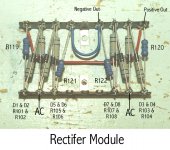
Why do you put resistors across the rectifier diodes? I seen caps when you don't want the abrupt turn off affecting LW/MW radio.
Sometimes both caps & resisters are used. I've done that on some multi KV PS's.This example is OK with only resisters sofar.
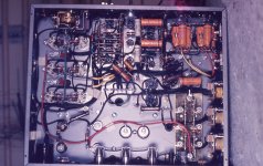
The photo is a 1.6KV, 0.25 Amp Constant Current PS. I think it ended up running a very early He-Ne Laser, hand built by one of the grad students in the lab where I interned. The PT secondary is 1715 volts. The diode bridge consists of six Philips PH103s with 2KV PIV rating. Looks like I used 2W resistors but no caps on this bridge.
The error amplifier is a 2-stage differential thing, all built along the -ve rail which happens to be barely off ground in this kind of application, so very few insulation problems. The diode bridge is in the lower RHS of the photo.
Wish I had more pictures all long ago circa 1960.🙂
Attachments
Yep I assume here its to make sure only half the total reverse voltage is across each diode as in your amp power supply. What a monster.
That PS never powered an amplifier, it is used to drive a constant current into a load that could vary randomly. The early gas based lasers were not very stable, the drop could vary from end to end. So a constant current was applied in this case.
Many of the people coming out of that lab went to work in the US. I got an offer from the U of Illinois digital computer lab. Then HP came, I stayed in Canada.😀
Many of the people coming out of that lab went to work in the US. I got an offer from the U of Illinois digital computer lab. Then HP came, I stayed in Canada.😀
Well guys, I'm keeping it as simple as possible with the limited number of existing tubes in the chassis, but I've filed the many ideas presented here for future design efforts.
I've nearly completed the circuit and implemented it in both channels.
This amplifier, with conventional bias of a fixed value, would draw 255 watts off the mains at idle.
With this modification involving signal responsive bias, the idle power consumption is 125 watts. At full output, the line consumption is 380 watts.
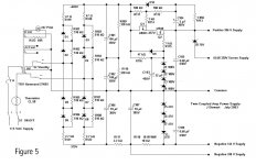
I'm taking the plate outputs through a high resistance network, blocking the DC and rectifying the result. The bias supply is -117 volts, regulated via a string of four 30V zeners. A resistive divider samples the bias supply and the signal rectifiers. At no signal, the bias on the KT88 grids sits about -85V. As signal increases, the bias is bucked by the output of the signal rectifiers sampling the plates and this voltage is summed with the bias supply. As signal increases toward full output, the bias voltage is bucked by the positive envelope voltage from the signal rectifiers, resulting in a maximum signal bias voltage around -35V. Using a 100V zener in series with a 100K resistor, tied to the -117V supply, I can limit the positive bucking voltage so that the bias never goes lower than -45V with maximum signal.
The only tricky aspect of this is getting the output tubes out of cutoff before significant signal appears. This limits me from having the outputs biased at -115V (which gets the line consumption down below 90 watts at idle). But I'm happy with 125W idle power consumption. The tubes run so cool that I can briefly touch the envelopes without pain. I expect tube life to be greatly extended via this signal responsive bias system.
I've nearly completed the circuit and implemented it in both channels.
This amplifier, with conventional bias of a fixed value, would draw 255 watts off the mains at idle.
With this modification involving signal responsive bias, the idle power consumption is 125 watts. At full output, the line consumption is 380 watts.
I'm taking the plate outputs through a high resistance network, blocking the DC and rectifying the result. The bias supply is -117 volts, regulated via a string of four 30V zeners. A resistive divider samples the bias supply and the signal rectifiers. At no signal, the bias on the KT88 grids sits about -85V. As signal increases, the bias is bucked by the output of the signal rectifiers sampling the plates and this voltage is summed with the bias supply. As signal increases toward full output, the bias voltage is bucked by the positive envelope voltage from the signal rectifiers, resulting in a maximum signal bias voltage around -35V. Using a 100V zener in series with a 100K resistor, tied to the -117V supply, I can limit the positive bucking voltage so that the bias never goes lower than -45V with maximum signal.
The only tricky aspect of this is getting the output tubes out of cutoff before significant signal appears. This limits me from having the outputs biased at -115V (which gets the line consumption down below 90 watts at idle). But I'm happy with 125W idle power consumption. The tubes run so cool that I can briefly touch the envelopes without pain. I expect tube life to be greatly extended via this signal responsive bias system.
That *is* an extra transformer.
You could end up doing like some of Kodabmx’s designs - with maybe 10 separate DC/DC converter modules providing all the different (including heater) voltages. And no AC inside to make hum. At all. Only downside is that you can never get that “classic” look with pretty 60 Hz transformers and chokes with nice painted end bells sticking out the top. People pay good money to see that.
Wel, my intention wasn't to replace any iron by SMPS's, but to provide a negative low current rail if there isn't any in a given amp or design. Surely there are many other possibilities for that.
Best regards!
Alternative Way to Create a Negative Supply
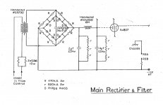
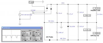
In all my SS B+ PS designs where a PT meant to run with a vacuum tube rectifier I've inserted something like 100R into the connexion between the rectifier cathode & the first cap. That 100R could just as easily be in the lead from the PT HV CT to common. Then the negative going pulses rectified & stored in an electrolytic. Here is one example & the -ve cathode lead it could replace.🙂
Only at very low singal levels.There isn't enough voltage for Q1 to fuction.
Like this it could work.
Mona
In all my SS B+ PS designs where a PT meant to run with a vacuum tube rectifier I've inserted something like 100R into the connexion between the rectifier cathode & the first cap. That 100R could just as easily be in the lead from the PT HV CT to common. Then the negative going pulses rectified & stored in an electrolytic. Here is one example & the -ve cathode lead it could replace.🙂
Attachments

This is called semi-automatic bias here in Germany and was used in many radios, especially those with their demodulation diodes combined with the power tube in one envelope.
Btw, wht does D3 do in your arrangement?
Best regards!
Btw, wht does D3 do in your arrangement?
Best regards!
A great question. Without D3 we would simply have back bias. The total volts available would be whatever the total B+ current was times that 100R. In this case that would be ~8.5V & would still need filtering.
The diode picks off the 24V peaks & dumps them into the cap, so more volts are available. The Zener sets whatever is required & a 470 nF Cap strips off any noise.
The diode picks off the 24V peaks & dumps them into the cap, so more volts are available. The Zener sets whatever is required & a 470 nF Cap strips off any noise.
Attachments
A great question. Without D3 we would simply have back bias.
For back bias, the resistor would be on the filtered side, wouldn’t it?
With this arrangement you’re rectifying (and filtering) the ripple voltage developed across it.
Last edited:
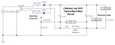
Typical Back Bias Circuit
Thought I could avoid this but by popular demand here is a typical back bias circuit. Right out of the 1930s, this was used in many receivers. Sometimes the choke was the loudspeaker field coil. If the resulting voltage was too great a simple voltage divider across the resister/choke was used. The resistances in series with the diodes go partway to simulating vacuum rectifiers. There are no toob rectifiers in the Electronic Workbench simulator, altho I've tricked it sometimes by fixing a triode so so it runs as a diode. That way the 3/2 power law gives a better solution to the simulation. To get even closer PT winding resistances need to be included. And electrolytic cap internal series resistance as well.
But a simple simulation is usually close enough to predict how the circuit will work on the bench.😀
Attachments
- Home
- Amplifiers
- Tubes / Valves
- Cathode Coupled Phase Inverter (sanity check)