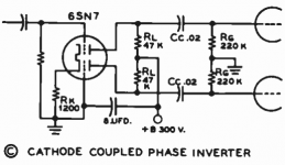
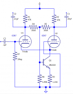
I'm revamping an amplifier design for a customer this week and opted to use the tried and true Cathode Coupled Phase inverter. I have a version of this with a transistor and a summing circuit to balance the outputs to within 1%, but the basic circuit as shown in the attached textbook diagram works to within 5% without any extra components.
I have an 807 amplifier that I built some years back with this circuit and it maintains perfect balance.
I've implemented it in the right channel of a home brew amp that a customer brought in. That channel had a balance problem on it's former See-Saw inverter circuit to begin with. I decided to redo it and use the cathode coupled PI, but it still won't balance.
The input A triode outputs X voltage, but triode B outputs X/2. I've gone so far as to put a 10K pot in place of Rk so that I could vary this value to see the effect. The best I could get was 50% mismatch.
I've tried various 6SN7 tubes in the socket, thinking that one triode was dead, but then I tried the 6SN7 out of my very good performing 807 amplifier, and got the same result.
I've checked the 47K plate resistors and they are spot on 47K. No obvious leakage on the input coupling cap. Plate voltages are within 5 VDC in both sections.
I've unplugged the output tubes (KT88s) to rule out some unexpected loading issues, but the imbalance remains.
Compared this same circuit in my 807 amp and the ac signal outputs are precisely matched to within a few millivolts at 40 volts AC signal on that unit.
The only variables are the chassis, tube socket and power supply.
Since the other channel's PI balanced reasonably well and this channel's did not, I'm suspecting a preexisting problem and am coming down to the point of replacing the socket itself.
I'm going to implement the CCPI in the other channel that didn't have a balance issue and see if it works properly there. If it does, then this will go down as one of the unusual cases where I have to change a tube socket because of some unknown crosstalk within the socket itself.
As a sanity check, I'm posting this for input from other tube techs. Maybe there's some stupid oversight I made. I'm dealing with advanced age and limited vision, so I could be overlooking something that a younger mind with sharper eyesight might pick up right away.
Attachments
Good plan to try the mod on the other channel. Does the 8uF decoupling capacitor work properly,
with no visible signal on it? If bad, that would cause a similar problem due to the common mode input.
with no visible signal on it? If bad, that would cause a similar problem due to the common mode input.
The length of the tail resistor is the issue. Taking only 18k worth of tail resistance requires about a 10% higher plate load to balance things acceptably. Ref the McIntosh 12AU7 stages in say a MC60, or 75. Or a MC30 or 40 for that matter.
cheers,
Douglas
cheers,
Douglas
The textbook example shows a 1.2K tail resistor. And I have used this version successfully in other amplifiers over the years. My refinement of the circuit uses an NPN transistor to act as Rk, sampling the summation of the two plate outputs. But in the case of this customer's DiY amplifier, increasing the tail resistor value makes the balance worse. As I approach 10K, the output of triode #2 decreases.
As for the cap driving it, even though I see no DC leakage on the grid, it is one of those "AudioCap" brand caps, so I've been eyeing it with suspicion. Seen too many of the 'snakeoil' caps become faulty in odd ways. Maybe I'll change that first.
As for the cap driving it, even though I see no DC leakage on the grid, it is one of those "AudioCap" brand caps, so I've been eyeing it with suspicion. Seen too many of the 'snakeoil' caps become faulty in odd ways. Maybe I'll change that first.
This is far from a good, balanced phase inverter. The cathode tail resister needs to be large in comparison to the plate resisters. That is one of the reasons why so many experimenters are using solid state tails now.
The Mullard circuit of the 50s & 60s popularized the long tail pair. Take a look at how they designed the circuit before SS devices to fit the tail were common. A simple improvement often seen was the 2nd plate resister higher resistance than the other so better balance was achieved.🙂
The Mullard circuit of the 50s & 60s popularized the long tail pair. Take a look at how they designed the circuit before SS devices to fit the tail were common. A simple improvement often seen was the 2nd plate resister higher resistance than the other so better balance was achieved.🙂
Attachments
" As I approach 10K, the output of triode #2 decreases."
Of course it does...in this condition the pair is nearly cut off; there is nearly no drive to No.2. With that 10k taken to -100V you will quickly discover that the performance is better.
cheers,
Douglas
Of course it does...in this condition the pair is nearly cut off; there is nearly no drive to No.2. With that 10k taken to -100V you will quickly discover that the performance is better.
cheers,
Douglas
It's interesting that the unmodified textbook circuit works well in earlier amplifier builds.
The fact that the right channel of the customer's amp was unable to balance it's see-saw PI leads me to believe something else is at play here. I'm going to duplicate the cathode coupled inverter in the left channel, which currently balances with it's see-saw inverter and see if it works properly. If it does, then I'm going to change out the tube socket in the right channel PI.
Attached is the modified circuit I used in my 807 amplifier, which works extremely well--balance to within 1%.
Attachments

Only at very low singal levels.There isn't enough voltage for Q1 to fuction.Attached is the modified circuit I used in my 807 amplifier, which works extremely well--balance to within 1%.
Like this it could work.
Mona
Attachments

Your 2nd circuit example is much better.
For the mathematically inclined, the long tailed phase inverter needs to satisfy the relationship
Rk(mu + 1 ) >> rp + Rl
So for the original circuit at post #1, plugging the numbers in & turning the crank
1200 ( 21 ) >> 7000 + 47000
25200 >> 54000 The relation fails.😱
The NFET tail fixes that.🙂
For the mathematically inclined, the long tailed phase inverter needs to satisfy the relationship
Rk(mu + 1 ) >> rp + Rl
So for the original circuit at post #1, plugging the numbers in & turning the crank
1200 ( 21 ) >> 7000 + 47000
25200 >> 54000 The relation fails.😱
The NFET tail fixes that.🙂
This is one of those instances where a circuit out of a textbook doesn't work well.
I replicated my 807 driver circuit with the transistor and balance/summing resistors and the inverter is working perfectly. Maybe the reason I implemented the transistor years ago was because of this problem and I simply forgot.
At any rate, I've upgraded the inverters on both channels of this DiY amplifier and it's performing very well, despite the KT88s still being on 500Ω cathode bias resistors. It's making about 40 wpc now at the 1% THD level.
Next is to realize more potential with eliminating the cathode bias and installing a C- supply.
And finally, if there's still time in the budget, I will implement a low idle current modification employing a MOSFET to modulate the bias voltage depending on signal level. I find that many tube amps will idle at low current, but suffer notch distortion at higher signal levels if the bias isn't made less negative. The variable bias will allow reasonably low distortion at near idle conditions, while increasing the current as the signal levels increase. Should be a lot of fun.
A negative “C-“ supply certainly makes things easier. A small $20 transformer solves a multitude of headaches. Longer tail resistors, more voltage headroom if you use a mosfet (so you stay in the region where Crss is low and linear), and you could even use a small signal pentode for the tail if you were dead set against using silicon. Not to mention fixed bias capability, or using direct coupled K-follower drivers which will often eliminate the distortion you’re referring to. I had no problem with notch distortion appearing at high drive with 6550’s biased at only 18mA (actually less during early testing) with direct coupled drivers.
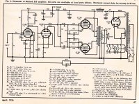
If I understand it correctly, Walsh is sensing the finals for current and sending a
control voltage to their bias to get closer to the original voltage swing of the driver.
control voltage to their bias to get closer to the original voltage swing of the driver.
Nice reference material from 1941. Not in any of my own textbooks.
However, I'm trying to take it a step further... not just autobias, but adjust the bias current depending on signal.
wg_ski, how did you direct couple your drivers? Was it a totem pole configuration to provide the right voltage stepping for the 6550 grids?
However, I'm trying to take it a step further... not just autobias, but adjust the bias current depending on signal.
wg_ski, how did you direct couple your drivers? Was it a totem pole configuration to provide the right voltage stepping for the 6550 grids?
I'm playing with sampling some of the plate signal on the output stage, rectifying it and applying it in a voltage divider to the bias supply. I've managed to get it to idle at -68V and swing to -51.5V at full output. This increased the short term pulse power from 68W to almost 80W, taking advantage of the filters in the PSU to provide short term power. The B+ rides higher with lower idle current, making this extra dynamic power realized.
The entire circuit is passive components.. a few resistors, two diodes, three capacitors. I'm going to tweak it some more. The target is to get the idle bias to -80V. The entire amp draws 125W at idle and 308W at full output with this dynamic bias. With conventional bias at a fixed -51.5V, the idle power consumption is about 230W. Being able to ditch adjustment pots and have the amp also run cool and extend tube life is a nice benefit.
The entire circuit is passive components.. a few resistors, two diodes, three capacitors. I'm going to tweak it some more. The target is to get the idle bias to -80V. The entire amp draws 125W at idle and 308W at full output with this dynamic bias. With conventional bias at a fixed -51.5V, the idle power consumption is about 230W. Being able to ditch adjustment pots and have the amp also run cool and extend tube life is a nice benefit.
wg_ski, how did you direct couple your drivers? Was it a totem pole configuration to provide the right voltage stepping for the 6550 grids?
They’re K followers. Fixed bias on the grid at about -44V, which puts the Vg1 for the 6550s at what it needs to be for about 18 mA. Three per side, each is independently adjustable. The tails are at -200V through 16.5k resistors. Light loading on the previous triode stage, no re-biasing or blocking distortion even at low bias, and well inside the 50k ohm limit for 6550s with fixed bias. Won’t happen without that negative supply - but it’s just such a small addition to the overall cost.
You probably need an active (regulated) PS?The target is to get the idle bias to -80V. The entire amp draws 125W at idle and 308W at full output with this dynamic bias. With conventional bias at a fixed -51.5V, the idle power consumption is about 230W. Being able to ditch adjustment pots and have the amp also run cool and extend tube life is a nice benefit.
You can replace R6 with a zener and supply the base of the 2n2222 straight from HT - although I like your approach. I prefer a transistor here as you get a big spread of possible currents with the Vgs of the mosfet. Good solution.

- Home
- Amplifiers
- Tubes / Valves
- Cathode Coupled Phase Inverter (sanity check)