Morgan owes me another beer. 😀
After you've read it, perhaps this story will amuse you:
http://www.diyaudio.com/forums/showthread.php?s=&threadid=99274
After you've read it, perhaps this story will amuse you:
http://www.diyaudio.com/forums/showthread.php?s=&threadid=99274
OK, while waiting for my "Valve Amplifiers" to arrive (coming by USPS, unfortunately), I decided to do some snooping around.
I found an RIAA calculator from GlassWare.com, but I don't know how accurate it is. I assume it's OK.
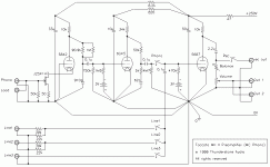
I found a schematic of the audio circuit for one of Arthur Loesch's RIAA preamps in an old issue of Sound Practices.
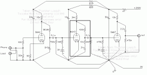
I also found Thorsten Loesch's Toccata MkII article, which is basically a version of the Arthur Loesch phono pre. Mine is a dumbed-down version of these.
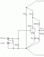
In this three-stage design, I can see that the 75uS filter happens in between the first 5842 stage and the second 6GK5 stage. This looks exactly like the 2122Hz Lo-Pass in the GlassWare calculator.
The 318uS and 3180uS poles happen between the 2nd (6GK5) and 3rd 5687 stages. This looks exactly like the 50Hz to 500Hz shelving as shown in the GlassWare calculator.
I couldn't see anything in the Toccata MkII (or Arthur Loesch's original circuit) that looks like the 500Hz to 2122Hz shelving in the GlassWare calculator. Is that part really necessary? Why is it apparently missing from the Toccata MkII?
Anyway, I modeled the Lo-Pass 2122Hz and 50Hz to 500Hz shelving filters in the GlassWare RIAA calc and came up with these...
Lo-Pass 2122Hz (75uS)
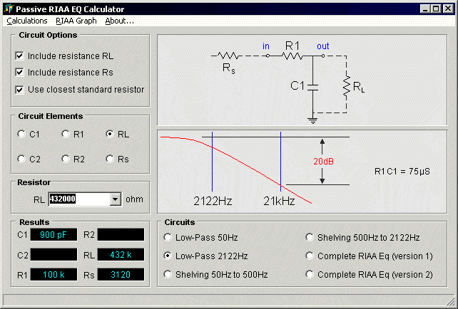
Shelving 50Hz to 500Hz (318uS and 3180uS)
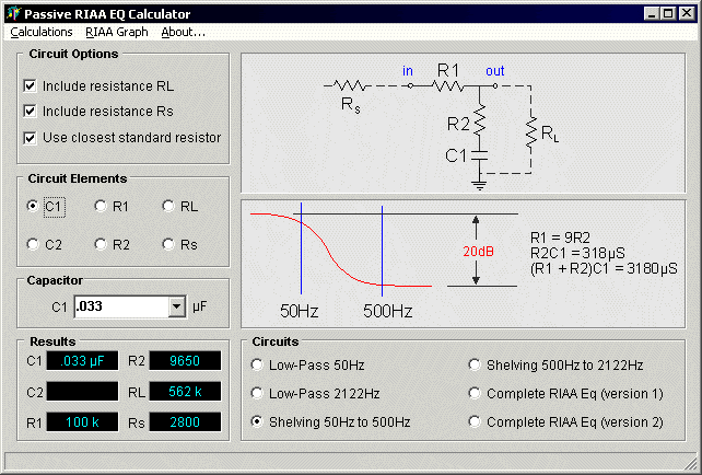
The Rs (series resistor) is the Zout of the preceding stage (c. 3100 Ohms out for 7788-triode or 7119; doesn't seem to change anything else if I reduce Rs to 2750 or so).
Does this look somewhere near to in-the-ballpark?
If the answer is, "Read Valve Amplifiers" then OK, I will, just as soon as I get it. Just couldn't wait. The important part I want to know is, why doesn't the GlassWare calculator's 500Hz to 2122Hz shelving filter appear anywhere in the Loesch RIAA?
Thanks...
I found an RIAA calculator from GlassWare.com, but I don't know how accurate it is. I assume it's OK.
I found a schematic of the audio circuit for one of Arthur Loesch's RIAA preamps in an old issue of Sound Practices.
I also found Thorsten Loesch's Toccata MkII article, which is basically a version of the Arthur Loesch phono pre. Mine is a dumbed-down version of these.
In this three-stage design, I can see that the 75uS filter happens in between the first 5842 stage and the second 6GK5 stage. This looks exactly like the 2122Hz Lo-Pass in the GlassWare calculator.
The 318uS and 3180uS poles happen between the 2nd (6GK5) and 3rd 5687 stages. This looks exactly like the 50Hz to 500Hz shelving as shown in the GlassWare calculator.
I couldn't see anything in the Toccata MkII (or Arthur Loesch's original circuit) that looks like the 500Hz to 2122Hz shelving in the GlassWare calculator. Is that part really necessary? Why is it apparently missing from the Toccata MkII?
Anyway, I modeled the Lo-Pass 2122Hz and 50Hz to 500Hz shelving filters in the GlassWare RIAA calc and came up with these...
Lo-Pass 2122Hz (75uS)

Shelving 50Hz to 500Hz (318uS and 3180uS)

The Rs (series resistor) is the Zout of the preceding stage (c. 3100 Ohms out for 7788-triode or 7119; doesn't seem to change anything else if I reduce Rs to 2750 or so).
Does this look somewhere near to in-the-ballpark?
If the answer is, "Read Valve Amplifiers" then OK, I will, just as soon as I get it. Just couldn't wait. The important part I want to know is, why doesn't the GlassWare calculator's 500Hz to 2122Hz shelving filter appear anywhere in the Loesch RIAA?
Thanks...
I want to add that I went through this exercise to try to keep the 100k series resistors and see if I could duplicate the RC values in the two Loesch pre's.
I'd choose 33k Ohm resistors for the series resistors, since I have a lot of them and they're about a decade above the source impedance of preceding 7788-triode or 7119/5687.
But first I wanted to see if I'm using the GlassWare calculator correctly.
Thanks again...
--
I'd choose 33k Ohm resistors for the series resistors, since I have a lot of them and they're about a decade above the source impedance of preceding 7788-triode or 7119/5687.
But first I wanted to see if I'm using the GlassWare calculator correctly.
Thanks again...
--
Your calculated values look about right.
Do you have a link to the Toccata schematic? I'm sure that the zero which creates the shelf is in there somewhere...
Do you have a link to the Toccata schematic? I'm sure that the zero which creates the shelf is in there somewhere...
rongon said:12AV7/5965 parelleled should also work, although I never see anybody using these (I wonder why...)
The 12AV7 is hideous.
An externally hosted image should be here but it was not working when we last tested it.
You can't find a loadline that comes in with a THD estimate under about 6.0%. and you just as well might use a BJT instead. One less hole to make, no heater power, and it'll sound just about the same.Even for RF use, you'd be better off using a 12AT7 (same Pd, higher u-factor). I can't think of anything more useless than the 12AV7.
Toccata MkII
webpage:
http://www.fortunecity.com/rivendell/xentar/1179/projects/toccata/Toccata.html
RIAA schematic:
http://www.fortunecity.com/rivendell/xentar/1179/projects/toccata/Toccata.gif
I would be using this version of the first stage (for high-output MC):
http://www.fortunecity.com/rivendell/xentar/1179/projects/toccata/Toccatamm.gif
Thanks. It would be very helpful if I could see (and understand) where this "zero that creates the shelf" is. Maybe something to do with load resistor value?
My plan is to use this circuit but to change it to stick with the tubes I'm already using. (E810F-triode > 7119 > 7119)
--
Miles Prower said:The 12AV7 is hideous...
Yeah, I thought the curves looked bad. I guess that's the same reason the 12BX7 was never used in place of 12AX7.
I once tried a 12AV7 as a cathode follower, DC-coupled to the final 12AX7 stage of an RCA phono preamp. It worked fine. Swapped in 12AT7 to see if I could hear the difference (biased up fine). It was about the same. I should've used a 6FQ7 or 12AU7, I suppose. I just wanted to try the 12AV7 and see what happened.
I promise I'll never attempt to use the two 12AV7s I have as a voltage amp of any kind. Maybe in a guitar amp...
--
The 12AV7 is hideous. You can't find a loadline that comes in with a THD estimate under about 6.0%
Strange..I've heard this before.
Just created a headphone/linestage with a GC/WCF (headwise OTL amp) and 3 x 12AV7's as I was curious. On another current thread.
I'm actually quite impressed with this tube. Very powerful detailed sound coming out of my speakers.
I've used 5687's, 6N1P's, 6N6P's and quite a few more.
Maybe I found a sweet spot of this tube. But I'm inclined to keep this as a fixed amp in my system. It has loads of punch and I liked it. Each to their own maybe or maybe I found the right combination.
I will publish my exact design.
The 5k and 62n form the zero you're looking for.
Changing from cascode (with an output impedance of the load resistor) to grounded cathode (with an output impedance of the load resistor in parallel with the plate resistance) will move the RIAA around a bit. Less so in this circuit than others, but certainly noticeable.
Changing from cascode (with an output impedance of the load resistor) to grounded cathode (with an output impedance of the load resistor in parallel with the plate resistance) will move the RIAA around a bit. Less so in this circuit than others, but certainly noticeable.
The 5k and 62n form the zero you're looking for.
I could increase the 5k resistor to ~10k and decrease value of the 62nF cap to ~33nF and come out with the same RC time constant, correct?
So the 5k and 62nF would be equivalent to the R2 (9659 Ohms) and C1 (.033uF) in this below?:

Something like this? (attached file ending in "ALTERED")
Attachments
Changing from cascode (with an output impedance of the load resistor) to grounded cathode (with an output impedance of the load resistor in parallel with the plate resistance) will move the RIAA around a bit. Less so in this circuit than others, but certainly noticeable.
Thorsten had this alteration to the first stage, for use with MM instead of low-output MC:
Attachments
rongon said:I once tried a 12AV7 as a cathode follower, DC-coupled to the final 12AX7 stage of an RCA phono preamp. It worked fine. Swapped in 12AT7 to see if I could hear the difference (biased up fine). It was about the same. I should've used a 6FQ7 or 12AU7, I suppose. I just wanted to try the 12AV7 and see what happened.
Cathode follower service isn't particularly demanding, since this is a feedback circuit. You could always use something non-linear like a 12AV7, wrap lots of NFB around it, and make what is essentially a glass op-amp. I still think it's better to use a more linear type so that you can go lighter on the NFB. It's better to make the open loop operation as good as possible, and add just enough NFB to improve on that, as opposed to using NFB to hide your design flaws.
I promise I'll never attempt to use the two 12AV7s I have as a voltage amp of any kind. Maybe in a guitar amp...
--
A guitar amp is a whole 'nother animal entirely. You don't necessarily want good linearity, and here something like a 12AV7 just might contribute to a desireable tone. That's probably where most of these are winding up, so far as audio applications are concerned.
You have to remember that this type was designed for RF amplification, where linearity doesn't matter since LC tuners and/or BPFs suppress unwanted harmonics. Use as a mixer/oscillator finds good linearity a detriment, not an asset.
Well, you're getting there, but R2 is really the combination of Rs (the output impedance of the 5687 at the operating point you have chosen) and R1 (47k) divided by 9 which will be somewhat larger than what you indicate. You then obtain the capacitor value by dividing 3180us by the combination of Rs + R1 + R2 which will be lower than 68nF. All this depends on the next stage having a very high input impedance and negligible input capacitance (i.e. a cathode follower). If it is an amplifier stage, like in the Toccata, it will interact with the 318 + 3180us stage and even Morgan needed a computer to work the sums out. If you use valves with high gain and a moving magnet cartridge you only need two gain stages.
Looking back at your diagram I see I've misread it and you have 43.7K which is 4.7K x 9, but you have missed Rs out of the equation. I think you would be better off using a standard value for R1 and a parallel combination for R2. 68nf will still be wrong as (Rs + 43.7k + 4.7K) x 68nF will be well over 3300uS.
Phew!
OK, I really need the Morgan Jones book. I know it's on its way...
It really is helpful to know what I'm missing, though. I'll have to leave this for today, but I'll try to pick up on this again, soon.
The first (75uS) stage was OK?
--
OK, I really need the Morgan Jones book. I know it's on its way...
It really is helpful to know what I'm missing, though. I'll have to leave this for today, but I'll try to pick up on this again, soon.
The first (75uS) stage was OK?
--
About the input stage, I'd have to work out the Rs figure for the 7788 (or E810F as we call it) which means finding my Mullard manual with the triode-connected figures in it. It looks reasonable, but why 9K for the anode load (10Ks are readily available in any flavour and wattage you want)?
Looking back at the diagram I see you're using a second section of the 5687 as a third stage amplifier which negates all the calculations of the 318 + 3180us section, as I explained.
I would use a higher gain second stage and employ the 5687 as a third stage cathode follower.
Looking back at the diagram I see you're using a second section of the 5687 as a third stage amplifier which negates all the calculations of the 318 + 3180us section, as I explained.
I would use a higher gain second stage and employ the 5687 as a third stage cathode follower.
- Status
- Not open for further replies.
- Home
- Amplifiers
- Tubes / Valves
- Cathode Bias questions
