Hey all,
This is turning into yet another very interesting thread. Thanks for sharing your knowledge. I was searching around this forum yesterday and saw some good stuff about grid stoppers, LED bias, Sakuma-style (CRCRCRC...) power supplies, LM317-regulated power supplies and CCS... All great stuff for me. I'm psyched.
Got myself (and my soldering iron) into the "heated state" last night. I picked up one of those grab bags of LEDs at my local Radio Shack and soldered a pair of red ones into the cathodes of the first stage of my phono pre (a work in progress...). Those went in place of the single 1N4148s that were already there. The stage went from:
7788/E810F triode wired
Rplate = 4kOhm (WW-NI 10W)
Ip = ~30mA
Ec = -0.75V
Ep = 90V
..to (with red LED in cathode):
7788/E810F triode wired
Rplate = 4kOhm
Ip = ~18mA
Ec = -1.9V
Ep = 150V
I thought that was too much bias (and plate voltage too high), so I changed the LED out to two 1N4148 in series:
7788/E810F triode wired
Rplate = 4kOhm
Ip = ~20mA
Ec = -1.5V
Ep = 115V
...And that's where I left it. I did like the red LEDs lighting up when the tubes warmed up. I'll definitely do something with that. Maybe in the line stage (1/2 5687 per side).
So I put the phono stage back in the system and cranked it all up. Spun a nice Wes Montgomery record. Big improvement. No more gnashing on the loudest peaks, yet still very dynamic. I think you were right, SY, that 0.7V bias was probably causing transient distortions, probably due to grid current on peaks. Do you think -1.5V is enough bias with a Denon DL-100 DC-coupled to the input of this stage? (DL-110 rated at about 2mV output.)
I also added a grid stopper (560 Ohm, carbon film) as I didn't have one at all. I'll bet that made things smoother too. Seems quieter. That might have helped as much as the re-biasing.
I lack test equipment, so I have to rely on ballpark guesstimates and listening for these things. I figure if I leave a large enough margin-for-error things will work out well enough for me. As you can tell, I only know enough to be dangerous !!
!!
If I post a schematic of my phono stage, would anyone be willing to critique it? I'm worried the RIAA is totally off, although I did try to do the math and it seemed OK. But I probably goofed up the math pretty good. Filter design is a bit beyond me still.
Thanks!
This is turning into yet another very interesting thread. Thanks for sharing your knowledge. I was searching around this forum yesterday and saw some good stuff about grid stoppers, LED bias, Sakuma-style (CRCRCRC...) power supplies, LM317-regulated power supplies and CCS... All great stuff for me. I'm psyched.
Got myself (and my soldering iron) into the "heated state" last night. I picked up one of those grab bags of LEDs at my local Radio Shack and soldered a pair of red ones into the cathodes of the first stage of my phono pre (a work in progress...). Those went in place of the single 1N4148s that were already there. The stage went from:
7788/E810F triode wired
Rplate = 4kOhm (WW-NI 10W)
Ip = ~30mA
Ec = -0.75V
Ep = 90V
..to (with red LED in cathode):
7788/E810F triode wired
Rplate = 4kOhm
Ip = ~18mA
Ec = -1.9V
Ep = 150V
I thought that was too much bias (and plate voltage too high), so I changed the LED out to two 1N4148 in series:
7788/E810F triode wired
Rplate = 4kOhm
Ip = ~20mA
Ec = -1.5V
Ep = 115V
...And that's where I left it. I did like the red LEDs lighting up when the tubes warmed up. I'll definitely do something with that. Maybe in the line stage (1/2 5687 per side).
So I put the phono stage back in the system and cranked it all up. Spun a nice Wes Montgomery record. Big improvement. No more gnashing on the loudest peaks, yet still very dynamic. I think you were right, SY, that 0.7V bias was probably causing transient distortions, probably due to grid current on peaks. Do you think -1.5V is enough bias with a Denon DL-100 DC-coupled to the input of this stage? (DL-110 rated at about 2mV output.)
I also added a grid stopper (560 Ohm, carbon film) as I didn't have one at all. I'll bet that made things smoother too. Seems quieter. That might have helped as much as the re-biasing.
I lack test equipment, so I have to rely on ballpark guesstimates and listening for these things. I figure if I leave a large enough margin-for-error things will work out well enough for me. As you can tell, I only know enough to be dangerous
!!If I post a schematic of my phono stage, would anyone be willing to critique it? I'm worried the RIAA is totally off, although I did try to do the math and it seemed OK. But I probably goofed up the math pretty good. Filter design is a bit beyond me still.
Thanks!
To me, they seem most useful with higher bias currents.Yes. But the real figure of merit is Z/Vf- one needs to series them to get a useful voltage value. With two in series, the forward voltage is about the same as a red LED and so is the impedance. How does their price compare to (say) one of the Agilent red LEDs?
Since they are rated at 1 Amp, there are situations where an array may not be convenient. They are $1+ Us currently for the 600V. There are / were a 300V flavor that may be less pricey.
Doug
Hello again.
Here's the schematic of my phono preamp. Actually, two schematics.
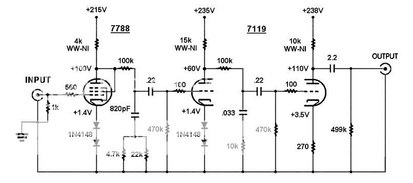
First the audio circuit:
And here's the power supply:
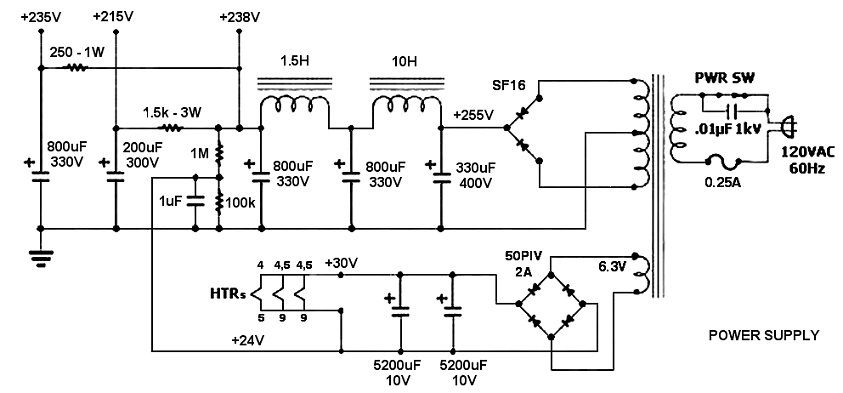
I know the power supply is dual-mono (separate xfrmrs for each channel, etc.) and yes, it's crude. The chokes were already in the chassis, as were the tube sockets, etc. I didn't intend to build anything this touchy, but I was (foolishly) trying to build a preamp for a Denon DL-103. The preamp turned out to be too noisy (both hum and hiss), but then I tried it with a high-output Denon DL-110 and found it to be a really good match! So I swapped in an appropriate load resistor and started tweaking. Then I found this site.
I'm enjoying the preamp's sound, but it seems a bit forward or edgy. It's better now that I upped the bias on the first stage, but I wonder if the RIAA is way off.
Or maybe I'm hearing the power supply's shortcomings. Resonances? Maybe those whopping big capacitors need to be scaled back, or bypassed with film caps?
OK, go ahead. Pick it apart. I'm ready!
Thanks...
Here's the schematic of my phono preamp. Actually, two schematics.
First the audio circuit:
And here's the power supply:
I know the power supply is dual-mono (separate xfrmrs for each channel, etc.) and yes, it's crude. The chokes were already in the chassis, as were the tube sockets, etc. I didn't intend to build anything this touchy, but I was (foolishly) trying to build a preamp for a Denon DL-103. The preamp turned out to be too noisy (both hum and hiss), but then I tried it with a high-output Denon DL-110 and found it to be a really good match! So I swapped in an appropriate load resistor and started tweaking. Then I found this site.
I'm enjoying the preamp's sound, but it seems a bit forward or edgy. It's better now that I upped the bias on the first stage, but I wonder if the RIAA is way off.
Or maybe I'm hearing the power supply's shortcomings. Resonances? Maybe those whopping big capacitors need to be scaled back, or bypassed with film caps?
OK, go ahead. Pick it apart. I'm ready!
Thanks...
I haven't checked the math on your RIAA, but a couple of things jump out at me. First and foremost is that first stage. I don't have triode curves for the 7788 at hand, but unless the plate resistance is really, really low, the plate load you have for it is throwing away badly-needed gain and operating the tube with a load line that is too steep. I'd explore increasing the load resistance and upping the B+.
Second, you could get more headroom in the second stage by increasing both B+ and bias. In an RC-coupled circuit, you want LOTS of headroom to prevent any chance of blocking distortion, which can really harsh things up.
It would be worthwhile running a frequency response check and tweaking the RIAA into conformance by adjusting the 100k resistors first. You can either build an inverse network or use a function generator (cheap and very flat) with an attenuator to drive the circuit, then measure the RIAA conformance directly. Getting that right, and very well-matched between channels, is a major pain but will make the difference between OK and excellent performance.
While you're at it, you might want to use a separate heater transformer or at least build in some common-mode filtering- the B+ supply will generate some diode noise which will couple very efficiently through the 6.3V windings and then into the tubes. The cathodes are pretty close to ground, which is good, but it's best to stomp out the noise at the source.
E810F Curves
Hi, these were posted quite some time ago on this site:
E810F Curves
on this previous thread:
Prvious thread
Should be of some use and fit what I've seen when biasing E810Fs in my (currently) stalled phono stage.
I was approximating ~5K for the plate resistance of the E810F in tiode.
Hope that helps a little
Ian, thanks.
With an rp of 5k, my point about the first stage is reinforced- getting that plate load higher will greatly increase the gain and lower the distortion and noise.
With an rp of 5k, my point about the first stage is reinforced- getting that plate load higher will greatly increase the gain and lower the distortion and noise.
This is a nice calculator for the RIAA components: http://www.hagtech.com/equalization.html
If you calculate the tube resistances accurately, I've found it very accurate.
Sheldon
If you calculate the tube resistances accurately, I've found it very accurate.
Sheldon
Sheldon, thanks for the link. NB: that calculator expects the poles to be the reverse of the circuit that rongon posted. Also, it is necessary to consider Miller capacitance, which that calculator doesn't.
With his cap values plugged in, the 100k resistors don't look so good. They'll need to be reduced to get RIAA conformance.
With his cap values plugged in, the 100k resistors don't look so good. They'll need to be reduced to get RIAA conformance.
Re: E810F Curves
Plate resistance is, theoretically, ~1K. The consistency of these tubes leaves something to be desired, and Gm is often a bit lower than advertised. This is, of course, a good place for an active load.
To the OP: take a look at the 6GK5. Lots of gain, lowish rp, much easier to work with than the 7788 which is a beast, and cheap. Oh, and linear and good sounding, too. They are what I used.
ianc13 said:I was approximating ~5K for the plate resistance of the E810F in tiode.
SY said:With an rp of 5k, my point about the first stage is reinforced- getting that plate load higher will greatly increase the gain and lower the distortion and noise.
Plate resistance is, theoretically, ~1K. The consistency of these tubes leaves something to be desired, and Gm is often a bit lower than advertised. This is, of course, a good place for an active load.
To the OP: take a look at the 6GK5. Lots of gain, lowish rp, much easier to work with than the 7788 which is a beast, and cheap. Oh, and linear and good sounding, too. They are what I used.
Yes, I see what you mean.
The only reason the 7788's are in there is because a 5842 I had blew up, and I was able to get four 7788's for cheap. I thought a triode-wired 7788 was very close to a 5842, which is why I tried it. But I'm flexible...
1) Replacing 7788: Problem with 6GK5 is that I'd need to fit 7-pin socket in a hole made for 9-pin. It could work, but would be a bit of a pain. I suppose I could do it, though...
What about a paralleled 6DJ8 in place of the triode-wired 7788? Enough gain (mu = ~32)? The gm would certainly be high enough and the rp low enough.
12AV7/5965 parelleled should also work, although I never see anybody using these (I wonder why...).
I also have a couple of 12BZ7's I could throw at this, but that would seem to me to be a step backward (rather low gm).
Parallel 12BZ7:
-------------------
Ep = 150V
Ip = 6mA
Ec = -1.0V
rp = ~15k Ohms
gm = ~6.4 mA/V
mu = ~90
Parallel 12AV7:
--------------------
Ep = 100V
Ip = 18mA
Ec = 1.0V
rp = ~3k Ohms
gm = ~12 mA/V
mu = ~40
Parallel 6DJ8:
-----------------
Ep = 75V
Ip = 20mA
Ec = 1.4V
rp = ~1.3k Ohms
gm = ~20 mA/V
mu = 32
2) Second stage: The raw plate supply in this chassis is limited to about 250V. It's 238V after the CLCLC sections. That doesn't leave me a lot of room to both increase plate resistance and keep bias high enough (over -1V) on the second stage.
What if I changed the second stage 15k plate resistor to 10k, like it is in the final stage? I could bring the Ip on the second stage up to about 15mA and get the rp down on that 5687 to about 2.5k Ohms -- in which case wouldn't a 10k resistor be a large enough value for the plate load?
Remember that I don't intend to use this preamp with low output MC's. Just high-output carts (Denon or Grado, probably). I have an old pair of Tamura step-up trannies which I could use if I somehow come into a DL-103 or whatever.
3) RIAA accuracy: I have to admit that I just took a circuit from JC Morrison (which was adapted from Arthur Loesch) and a friend of mine tweaked it a bit and basically said, "Try this." I don't have the chops to come up with something like that from scratch.
I'll plug values into that RIAA calc and see if I can come up with something.
Maybe I should reverse the order of the filters to match the calc.
Thanks, y'all.
--
The 7788 should work OK if you run it more advantageously (higher plate load and B+) and tweak the network. If you want to be ultra-outre, you could even make the first stage a cascode with a low noise FET on the bottom....
I've had very, very poor experience with 12BZ7. It's theoretically a doubled 12AX7, but my measurements have shown it to be much less linear and the sound is consistent with that result.
I've had very, very poor experience with 12BZ7. It's theoretically a doubled 12AX7, but my measurements have shown it to be much less linear and the sound is consistent with that result.
BTW, if you haven't already, I'd study very carefully the treatment of design and calculation for RIAA stages in Morgan Jones's "Valve Amplifiers" 3rd edition. He covers topologies very similar to yours and rationalizes the proper order of EQ sections. I do things differently than he does, but did so with my eyes open.
Here is another RIAA calculator that I have used with success.
http://www.kabusa.com/riaa.htm
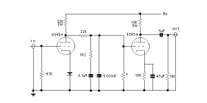
I have built very good sounding single stage passive RIAA around the teflon russian caps found cheap on Ebay. .1uf and .033uf
http://www.kabusa.com/riaa.htm
I have built very good sounding single stage passive RIAA around the teflon russian caps found cheap on Ebay. .1uf and .033uf
Attachments
Thanks greenvalve.
The resistor marked with * in the schematic, that looks like a grid-leak resistor. What value do you choose? 10M? Do you calculate/adjust the value of the grid leak resistor to obtain your desired bias point for the second 6S45Pi? Does this grid leak resistor change the RIAA slope at all?
I see you chose a 33k Ohm resistor for the plate load on the first 6S45Pi. That would mean a rather high B+, wouldn't it? That 33k plate resistor would drop 330V at only 10 mA, and I know the 6S45Pi can take a lot more current than that. Are you running the first stage 6S45Pi at a very low plate current?
I like the direct coupling of the two stages, but wouldn't that cause possible problems from record warps?
The chassis I'm working in already has two 9-pin sockets installed, which I'd like to keep using. It originally had one of those (common) two-stage RIAA circuits with each stage followed by a cathode follower.
--
There is quite a variance with the 6s45p tube, so the *R is actually a 1M 2W pot, I use it as you said, to fine tune the bias on the second tube. Even that does not guarantee a particular tube will function as hoped. B+ is around 425V and the plate voltage is around 100V on the first tube IIRC. Too much current through these tubes and the third-order harmonics start becoming audible. Stunning bass, no problems with warp or drivers bottoming out. If your worried, reduce the value of the output cap. The 6s45p is a single triode, so you would need four 9-pin sockets. I've build many phono stages and I like this one the best. It has enough gain to eliminate an entire stage, and another coupling cap, so that is probably part of it's good sonics.
The good value part of this phono stage is the use of the teflon russian caps. Perhaps there is another tube that would function well with the 22k RIAA loading resistor and the .1uf / .033uf caps. There are some unappreciated good sounding high gain 7-pin tubes out there.
The good value part of this phono stage is the use of the teflon russian caps. Perhaps there is another tube that would function well with the 22k RIAA loading resistor and the .1uf / .033uf caps. There are some unappreciated good sounding high gain 7-pin tubes out there.
Thank you everybody for all the info.
I changed things up a bit and have the preamp sounding pretty decent, if I may be so bold. It's very detailed, which I like. I think it's a bit too bright, though. Probably an EQ problem, but for now at least I have a working preamp that plays music. It doesn't seem to crunch and it sounds very involving. Gobs of texture, which I like. I guess that's the 7788 in triode as the input tube.
I rebiased the second stage, putting in a red LED for Eg = 1.8V. Changed the plate resistor to 11kOhms (that's 43kOhm in parallel with the 15k that was there). The current through the tube went up a little, from 13 to 15mA. That seemed to let the sound breath a little easier. Maybe it kept the second stage from getting too close to overload.
Then I tried changing the first stage to the following:
7788 triode wired
-----------------------
Ra = 15kOhms
Ea = 90V
Eg = 1.4V
(two 1N4148 in series in cathode)
Ia = 10mA
That changed the sound quite a bit. Unfortunately, I didn't like it. It sounded grainy and anemic. Everything sounded 'softer', but in a vague way. Maybe a 7788 in triode needs at least 15mA to sound good?
So I changed it to something else.
7788 triode wired
-----------------------
Ea = 90V
Ra = 9kOhms
Eg = 1.0V
Rk = 60 Ohms
Ia = 16mA
Now I like it. It sounds much bigger, stronger, clearer. I figure the tube's internal plate resistance is about 2kOhms, so 9k for a plate load is marginal, but it should be enough to operate at reasonable distortion. I hope a 1V bias is enough to keep it out of grid current. So far it seems OK.
--
I downloaded the Tube CAD Journal RIAA calculator. I plugged in the capacitor values I have in the circuit, and the Rs and Cs seemed to line up pretty well with the desired time constants -- except for the series resistor, which it showed should be 120k.
As ri (internal plate resistance) of the tube goes down, does the series resistor need to be increased in value to compensate? In the discussion of the "El Cheapo Valve preamp", someone asked if using a paralleled 12AX7 in the first stage would be a good idea. The answer seemed to be that it could work, but the series resistor would need to be increased from 215k to 270k to compensate. No way to plug the previous stage's output Z into the equation, so I dunno...
Apart from that, the values seemed pretty close, and the preamp sounds pretty good as it is now, so I'll stop stressing it and spin some more records.
But now, I'm thinking of building something right for a change...
--
I spent a few hours searching around the site and reading what folks had to say about small signal tube types, RIAA circuits, etc.
I've seen that a lot of folks say the split RIAA filter topology sounds better. The Hagtech Bugle uses this. Does this require three gain stages to work? If only two gain stages are used then must a cathode follower be put on the end (to isolate output from loading down into subsequent cables, stages, etc.)?
I also saw a comment that a three stage RIAA preamp for moving magnet cartridges could be made using low or medium mu tubes. This is almost what I ended up with (by accident). That would make a split RIAA possible. Is this something that makes sense, or is this doomed to sound less than ideal?
On the other hand, greenvalve mentioned that a combined RIAA network allows the use of only two stages. Less is usually more in audio, so I like that too. But then again, there are some who claim that a combined filter network with multiple poles and time constants interacting in unknowable ways will cause a loss of sound quality in the subtle things like "detail," "transparency" and all that good stuff.
(I'm the type that likes Jordan modules as compared to B&W 801, so I guess I'm in the simpler-filters-are-better camp.)
At any rate, there are tools available to design a combined RIAA network from scratch, so maybe that's what to do. First step, choose the tubes. I want this project to have the following qualities:
1) It shouldn't require a power supply the size of a small power amp. Something like 60mA total current would be nice. Heater supply should be about 2A. B+ shouldn't be too high. Something with a raw supply of +350V or less would be nice. 500V electrolytics are expensive (and I don't have any more).
2) I like a fairly relaxed sound, but with detail. Something that would tame the Denon cartridge's zippy tendencies would be nice. I'm not a fan of '60s "tube sound."
3) I can't invest a hundred dollars in exotic tubes.
4) It should be fairly easy to get to work successfully. I think that rules out two stages of 7788-triode for me. That's a fussy tube, and I only have four of them. It's also an expensive tube here in USA...
I looked in my tube collection. I've got lots of 6DJ8 tubes. Mostly Phillips/Sylvania JAN. I also have a ton of 5687WB Phillips/Sylvania JAN and a few Tung Sol. That's it for high gm types.
So, here's the last question:
Would two stages of 6DJ8 make a usable RIAA pre?
Is it true that the 6DJ8 only makes a decent sounding first stage in a cascode or SRPP arrangement?
A 6DJ8 run as a regular old plate loaded triode stage won't sound good? Even with 15mA running through it and an LED in the cathode? You mean to tell me a 12AX7 makes a better first stage in an RIAA pre than a 6DJ8?? Any idea why? High distortion? "Blah" or "raspy" sound?
On paper, a 6DJ8 with a decent amount of plate current going through it looks almost ideal -- it's got high-ish gm, enough voltage gain and a fairly low plate resistance. Looks to be in a linear region with 15mA running through it and about 90V on the plate.
OK, time to play another record. I'd be happy to hear from someone who's messed around with this. Thanks!
--
Would two stages of 6DJ8 make a usable RIAA pre? Is it true that the 6DJ8 only makes a decent sounding first stage in a cascode or SRPP arrangement?
In order:
Yes.
No.
edit: the only issue (assuming competent design) is gain. Two 6DJ8 run optimally will provide a gain of roughly 60dB. With a 20dB loss at 1kHz, the RIAA standard, that yields a gain of 40dB at midband. For a 5mV cartridge output, this corresponds to 500mV of output. If the line stage can boost that to the 2-3V needed to drive a power amp, you're fine. If you have a unity gain or passive line stage, this won't be quite enough.
I like the sound of 6DJ8, it would make a good phono tube. Also the russian 6n1p-ev is very good sounding. Just try it and see what you think.
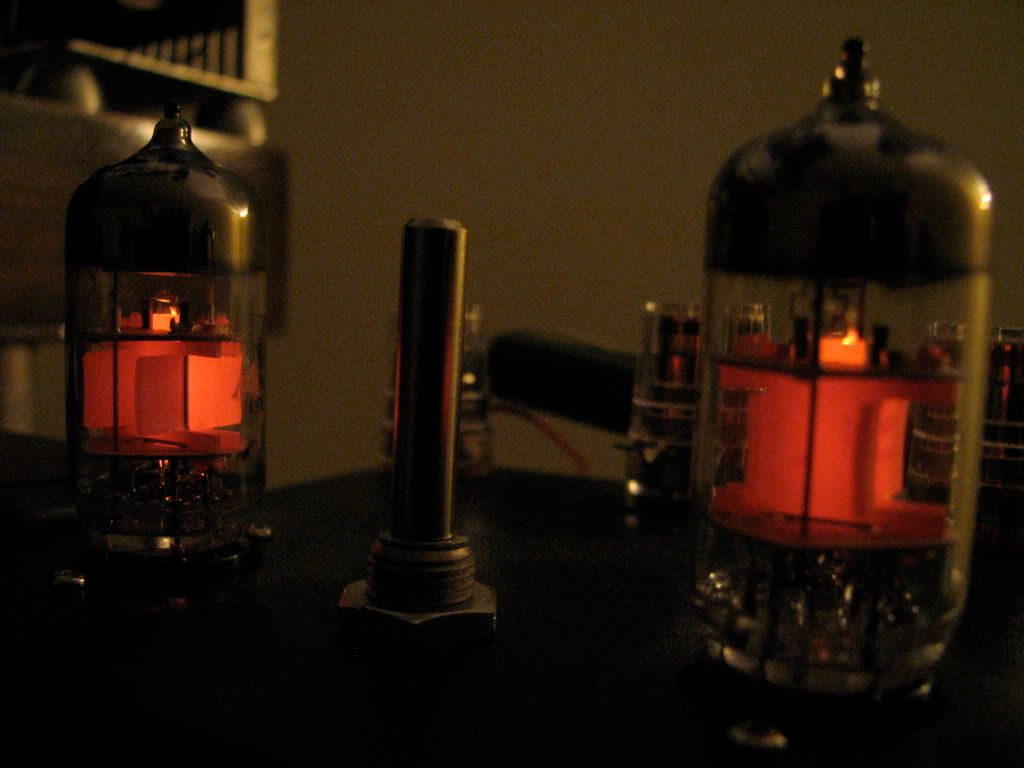
Here is a picture of my 6s45p spud amplifier. The tube can conduct some current i guess 😉
http://www.facebook.com/video/video.php?v=1183283348477&ref=mf
Here is a picture of my 6s45p spud amplifier. The tube can conduct some current i guess 😉
http://www.facebook.com/video/video.php?v=1183283348477&ref=mf
- Status
- Not open for further replies.
- Home
- Amplifiers
- Tubes / Valves
- Cathode Bias questions