The actual circuit will be fed with a jfet current source. I'll be using the same source to feed two ring of two circuits.
Gives a good performance gain making that CCS a cascoded JFET scheme. If you happen to have a pair of JFET part types with >2x Vto difference handy, no real added complexity.
a little more playing in sim and I don't find meaningful "cascode" advantage in your circuit - just sim the "ring of two" by itself - I used the Fairchild mpsa92/mmbya92 datasheet spice model
if you read Hawksford though you can get to Sy's cited |100 Meghom| output Z in sim with 3 bjt transistors
http://www.essex.ac.uk/csee/research/audio_lab/malcolmspubdocs/J10 Enhanced cascode.pdf
this "enhanced cascode" functionality can be added in your circuit with just 1 added Cap - although it needs to be high enough value that electrolytic would be the choice
Last edited:
Hmmm.. Thank you for continuing to think about this... My goal in presenting this circuit was a reasonable bipolar current source that didn't take a lot of current to drive. This proviso automatically nixed the LED-biased cascoded sources seen in the literature. I doubted from the start that a simple ring of two source would offer up the proper output impedance (everyone else was using cascodes, after all...), so I proceeded directly to the cascoded ring of two. Now you're telling me that the cascode doesn't offer much extra in terms of output impedance. I want to go back to PSpice with the models there to see if this is confirmed with the tools I have available. I found it interesting that a diode-biased cascode current source was actually slightly inferior (~10% difference) to the cascoded ring of two. I also found that adding an extra cascode transistor to the cascoded ring of two in simulation did absolutely nothing for the output impedance. Is this true, or are the models lacking?
I originally modelled the circuit to see if there were any stupid Duh! types of mistakes that would keep it from working. Not so, it turns out. I also wanted to compare it to extant bipolar curcuits to see roughly how it compared.
At any rate, I want to take some time to look at the extra information you cite and see if I can understand what is going on. It may be worthwhile to measure the output impedance of actual circuits to see if there is something that is missed in simulation, adding to the information that is already available on mosfet-based current source loads.
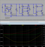
a big Cap (100u C3) aproximates a Vsource coupling the cascode base to the emitter of current controlling Q - what Hawksford calls "enhanced cascode" - although his analysis and measurements are useful he really wasn't 1st with these circuits - or cite their origins in his paper
the AC short of C3 captures the Zcb current of the cascode Q and puts it back into the regulated current - giving ~ 100x (simmed) improvement in output Z over much of the audio frequency range
you can edit the C3 value to fF to compare the original post' ccs to the 2 bjt version on the right - they are very close
high gain Q seems to give a tiny bit better simmed performance than the 2n4403
Attachments
Last edited:
Is it possible to use a single bjt as the CCS load? For decent operation that is better than a resistor load? Don't know much about CCS' so hopefully this is a smart question to ask. As always, constructive criticism is welcomed.
Sure.
Like here (it is a real high end):

ccs plate load with rload
thanks for the tips on the other threads--I accidentally unsubscribed, so thanks especially to Wavebourn.
How is it that the ccs only works when connected to RL, which I wanted to get rid of? If I bypass RL & connect CCS directly to the plate, I lose gain, but when I connect the CCS to RL, which then connects to plate, I get gain, the circuit works, etc.
None of the schematics furnished show CCS connected to a plate resistor, so I'm curious. It'd be nice to save space on my crowded projects by eliminating RL.
Earlier in this thread, I saw "hundreds of Meg Ohms".
I think that would be from a simulation using the junction cap compensation by Hawksford. Intended for SS circuits too.
It is wonderful to create a topology to 'negate' the capacitance, that is great engineering.
But we still use conductors to connect a low capacitance circuit to the outside world.
Creating a low capacitance circuit like 0.08pF, is like worrying about the very last inside layer of the onion, when we have not yet peeled the hard skin off the outside of the onion.
But we still use conductors to connect a low capacitance circuit to the outside world.
Creating a low capacitance circuit like 0.08pF, is like worrying about the very last inside layer of the onion, when we have not yet peeled the hard skin off the outside of the onion.
- Status
- This old topic is closed. If you want to reopen this topic, contact a moderator using the "Report Post" button.
- Home
- Amplifiers
- Tubes / Valves
- Cascoded Ring of Two for Plate Load