I've been looking at using a cascoded ring of two as a plate load for one of my preamp projects, as it requires less bias current than a cascoded bipolar current source using an LED reference. The circuit is shown in the attachment. Values are currently set fo 3 mA current. The AC source shown in the schematic was used to check the output resistance of the circuit - I got about 4M. Things may be a little better if I set a smaller step time and tolerance for the simulation.
Any way, food for thought...
Any way, food for thought...
Attachments
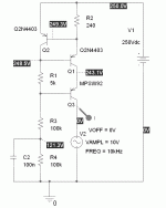
C2 has no purpose in a simulation as all the sources are perfect and squeaky-clean. In the real world it would clean up the feed to the ring of two control transistor. Papa uses this trick on some of his earlier Zen amps. I may just use a JFET current source at the bottom instead, so that the line rejection is improved and the control transistor has a well-defined current against which to work.
Anyway, I was exploring this option since the usual depletion mode mosfets are reputed to not work so well at low current, and I didn't like the idea of ramming 5-10ma into an LED reference just to jazz a 2-3ma current source. I'm trying to limit how much I draw from the B+, as I'm planning on generating it in a somewhat unconventional manner. I also have loads of 2N4403 and MPSW92, as well as a Fairchild TO-126 video driver transistor for higher currents.
Anyway, I was exploring this option since the usual depletion mode mosfets are reputed to not work so well at low current, and I didn't like the idea of ramming 5-10ma into an LED reference just to jazz a 2-3ma current source. I'm trying to limit how much I draw from the B+, as I'm planning on generating it in a somewhat unconventional manner. I also have loads of 2N4403 and MPSW92, as well as a Fairchild TO-126 video driver transistor for higher currents.
I tried a simple Jone/SY-type bipolar cascoded current source in simulation using a stack of 3 pieces of 1N4003 instead of the LED for biasing. The bottom transistor was a 2N4403, cascoded with an MPSW92.The diode stack was biased at 5ma, and the current source was set to deliver 3ma. Output impedance was around 9M, very similar to the cascoded ring of two source.
The ring of two cascode simulates as having slightly better output impedance than the classic LED biased cascoded bipolar source (10M vs 9M), with far less maintenance bias current (0.5-1ma vs 5 ma). If no one finds an obvious hole in the design, I'm going to try this approach for the 6J6 version of my "Evil Sandman" preamp. No pretty lights, but I can live with that.
Yes, but will they work well at 2-5 ma? I have another circuit (see the "Evil Sandman" thread) using a triode-connected high gm pentode that will be running at 20ma current to fully exploit its "goodness". I intend to use depletion mode fets as a load there.
At any rate, I ran simulations for the bipolar current sources to compare the simulated performance of the ring of two vs the LED-biased cascode sources, in order to get a figure of merit. The simulation is only as good as the models, and the some transistors/models were used for both. They both appear to be roughly equivelent, with the ring of two circuit being slightly better. Real-life performance may be different, but I intend to try it and see. I figure it'll be good enough for a 6J6...
At any rate, I ran simulations for the bipolar current sources to compare the simulated performance of the ring of two vs the LED-biased cascode sources, in order to get a figure of merit. The simulation is only as good as the models, and the some transistors/models were used for both. They both appear to be roughly equivelent, with the ring of two circuit being slightly better. Real-life performance may be different, but I intend to try it and see. I figure it'll be good enough for a 6J6...
Yes, but will they work well at 2-5 ma?
In theory, even better, since the source resistor will have to be larger.
I'll still use the bipolar source for the 6J6 preamp, as it's supposed to be a cheapo affair. Having said that, that means I'll replace the mosfet current source in the line amp/output buffer (as shown in the "Sandman" thread) with a bipolar current sink to be more true to the concept. If I get them done in time, the 6J6 preamp and its snootier cousin may show up at this year's BA, along with a motley assortment of power amps.
C2 has no purpose in a simulation as all the sources are perfect and squeaky-clean. In the real world it would clean up the feed to the ring of two control transistor.
It would be easy enough to check using your simulation, but I think that capacitor actually injects noise into the reference.
It would be easy enough to check using your simulation, but I think that capacitor actually injects noise into the reference.
Ideally, the two resistors (R3 and R4) would be replaced by a current sink. Turtles all the way down.
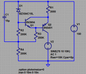
Baxendal "super pair" sims well, gives cascode equivalent output |Z| > 10 Meg @10KHz
using more V for ref and none for "cascode" evens out: simmed with 10 V zener - may want lower noise ref if you "shave" the bias, or added RC filtering between Zener and Q1 base
may show ringing without some load C ~ single digit pF probably already in a real circuit
even "regular cascode" ccs often show instability/ringing step response with high Z load
I just used the LtSpice supplied models:
Attachments
Last edited:
I've been looking at using a cascoded ring of two as a plate load for one of my preamp projects <snip>
Any way, food for thought...
I see, I think (I think). Is that circiut also known as a current mirror?
I've been away from electronics at the schematic diagram level for a long time and just started reading up again. I have seen something like that only with NPN transistors and drawn upside down from your circuit.
I'm lookig for a plate load cicuit that will do 10 ma at several KV!
Do you think that is possible with solid state? Well it must be because I used to work at a place in the '80,s where I repaired these special amps that could output a 4.7us 1500 v p-p square wave, but I don't remember anything about the circiutry. I just replaced stings of TO-3 MOSFETS. What do you think?
Jim
C2 has no purpose in a simulation as all the sources are perfect and squeaky-clean. In the real world it would clean up the feed to the ring of two control transistor. Papa uses this trick on some of his earlier Zen amps. I may just use a JFET current source at the bottom instead, so that the line rejection is improved and the control transistor has a well-defined current against which to work.
I think you refer to the D. Self one Vbe CCS bootstrap cap to B+.That one is in Zen. Increases PSRR. The capacitor needs some ESR not to cut a V in the PSRR curve BTW and to be tied to psu, not gnd. As it is I am afraid it will just feed gnd noise to the ref.
- Status
- This old topic is closed. If you want to reopen this topic, contact a moderator using the "Report Post" button.
- Home
- Amplifiers
- Tubes / Valves
- Cascoded Ring of Two for Plate Load