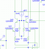
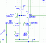
Yes, the leftmost schematic holds the cascode at a fixed voltage above GROUND, while the rightmost holds the cascode at a fixed voltage above SIGNAL.
The first runs into overload at very high inputs, and varies the Vce of the input devices. The second has much higher overload, and holds constant Vce on the input devices, eliminating Early effect.
The second is preferable, in my opinion.
Hugh
The first runs into overload at very high inputs, and varies the Vce of the input devices. The second has much higher overload, and holds constant Vce on the input devices, eliminating Early effect.
The second is preferable, in my opinion.
Hugh
Yes the second, its constant Vce for input transistors increasing its linearity (more precise). Choosing input transistors with constant Vbe at specific current region (look at its Ic-Vbe graph) will result a highest linearity.
Last edited:
😕 Where that rules coming from? I am using 470ohm to convert shunt resistor's voltage into current pecisely. 470 is far from that rules.The emitter resistors are way too large. They should be less than 100 ohms.

Cordell tells us to use the emitter resistors to adjust the gain of the input stage.
He suggests choosing a degeneration value of 10times, but also tells us that this can be any degeneration value.
Some others suggest the Vdrop of Re should be ~half to 100% of Vbe of the input transistors.
Leach shows in detail why he chose 330r in the Lo Tim.
There are lot's of rules. Find the one that suits your compromises. Expect Re from 10r to 1000r.
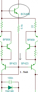
The collector current times the emitter resistance is the max. voltage on the input. 100 ohm emitter resistor and 1 mA collector current tells us that 0.1 V is the maximum you can apply to the stage before clipping. some designers use this to design amplifiers with little TID. Without global feedback the resistors have to be large, and/or the collector current have to be large. I don't think you can apply a rule to the size of the emitter resistors if you don't see it in connection with the collector current.
The amplifier is the End Millennium. Original schematic use 2k.
I do notbuilt the original amp, I only use 3 stages. Sound very good.
I was try using cascode input stage and VAS, just for see any different and I was read this two cascode configuration.
I will try with the second configuration 😉
Now, wich is the Vce "optimus" voltage?
Supose that I use Vcc=25V and Vee=-25. A low Vce value (4,7V) is more desirable that a higher value (12V)?. Or it does not matter? reffering on the input stage.
you require good performance from the input device.
You look at the options and decide which compromises introduce less distortions/heating/capacitance/unwanted effects.
This may be operating at Vce=2V or at Vce=125V or anywhere in between.
Some designers/builders ear tune to a sweet spot.
I have not heard this so cannot comment on the reliability of finding an accurate sweet spot.
AKSA and Ostripper and others have ear tuned and reported impressive results.
Many very good commercial equipment manufacturers ear tune for popular sound output.
Last edited:
Yes, the leftmost schematic holds the cascode at a fixed voltage above GROUND, while the rightmost holds the cascode at a fixed voltage above SIGNAL.
The first runs into overload at very high inputs, and varies the Vce of the input devices. The second has much higher overload, and holds constant Vce on the input devices, eliminating Early effect.
Hi, Hugh
I'm a little bit confused here.
Assuming that "the first" is the left schematic and "the second" is the right schematic, I'm failing to see how in the second one the Vce of the transistors is held constant - since the reference is the signal - and the signal is not constant. Maybe I'm missing something...
Please shed some light over it.
Regards,
Tibi
Cordell tells us......
Leach shows.....
There are lot's of rules. Find the one that suits your compromises. Expect Re from 10r to 1000r.
Thanks Andrew, I just follow what I need to achieve, lower resistor value result in higher gain, and with higher resistor value it will more linear.
Hi, Havenwood,
Place extra transistor at their emitter connection to draw less current from it. I like to use around 7V or 8V Vce.
Attachments
- Status
- Not open for further replies.
- Home
- Amplifiers
- Solid State
- Cascode input question