Edit: I just figured out the first post is a editable, so is a good place to keep up-to-date design docs without forcing people to wade through pages of guff.
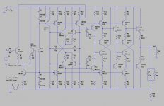
Post # 151 (http://www.diyaudio.com/forums/soli...eap-low-thd-10w-amp-tip41c-4.html#post5307265) has attached current (as of 13 Jan 2018) design for a super-cheap low distortion amplifier using BD179 & BD180 output drivers. I'm rating it for 5W into 8 ohms, a little more into 4 ohms. It's just the ticket for driving tweeters and little full-range speakers. I'm thinking it'll be a useful 50 ohm line driver too.
I've attached .asc file, .zip of KiCAD source and gerbers, screen shots showing where everything is on the PCB, schematic screenshot, simulated behaviour pushing 10V pk into 8 ohms, simulated square wave response, simulated clipping, open loop gain and closed loop gain.
I've got the real thing sitting on my desk as I type playing music through a little 4" PC speaker, and it sounds like an amp that's not adding anything to the music.
Attachments
Last edited:
Oh dear. Now I just have to get a move on with the line arrays.
Given that this is a ground up design, is there any advantage in making a higher voltage amplifier to drive more than one TC9 in series?
Graham.
Given that this is a ground up design, is there any advantage in making a higher voltage amplifier to drive more than one TC9 in series?
Graham.
Yes very nice circuit, but why do you take the poor TIP?
Why don't you take some of the old known IRF-Mosfets? They are also cheap, but much better...I think.
Why don't you take some of the old known IRF-Mosfets? They are also cheap, but much better...I think.
Oh dear. Now I just have to get a move on with the line arrays.
Given that this is a ground up design, is there any advantage in making a higher voltage amplifier to drive more than one TC9 in series?
Graham.
Higher voltage means I have to ditch the 2N3904/3906 & 2N2222/2907 in favour of higher voltage parts - say MPSA06/56...
I'll have a play. Parallel might be easier, as it can be accomplished with more output devices.
I'm also playing with 3 sets of BD179/180 in lieu of the TIP41/42, simply because it allows me to spread the current source load across 3 transistors, and I can then use 2N3904/3906 rather than the BD139 there (higher gain), which in turn reduces current requirement for my reference.
I would be interested in a 300W 8 Ohm version.
That's not at all what this amplifier is.
Yes very nice circuit, but why do you take the poor TIP?
Why don't you take some of the old known IRF-Mosfets? They are also cheap, but much better...I think.
Vgs on a MOSFET is ~2-4V, vs Vbe for a bipolar of ~0.6V. MOSFETs will need higher supplies.
Series with higher voltage benefits class-b (ab, what have you) biasing conditions as you stretch/smooth out the crossover region*. Plus you can double your budget per amp. 😉
*Distortion In Power Amplifiers Figures 15-23
*Distortion In Power Amplifiers Figures 15-23
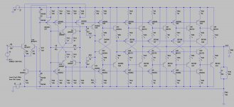
Swapping from TIP41/42 to BD179/180, driving 4 Ohms (2 x TC9 speakers in parallel), and consolidating most of the low-power transistors to 2N3904/3906.
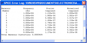
Still managing <1ppm THD at 10KHz, 20W.
I calculate cost to be ~$12 per amp for components, not including PCB, power supply, etc.
I tried a symmetrical-differential input stage, and while it improved THD a little, the output offset blew out from <3mV to >30mV, so I wouldn't really be able to do that without a large (expensive) DC blocking cap in the feedback network.
Attachments
Impressive. Looking at the highly symmetric circuit pleases the eye.
In order to turn it into a more versatile amp (power is enough, if really high quality), one would need something like output coil and estimation of stability. Just to directly connect to some driver, this probably is not necessary.
And how about PSRR? With a comparably cheap supply this becomes an issue. Is it possible to decouple the input stage rails somehow? Or is it not necessary?
Kind regards,
Matthias
Last edited:
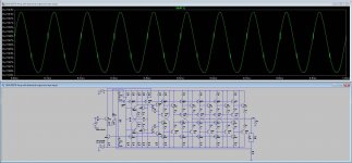
I'm getting these glitches in the waveform up to the driver stages.
Where do they come from and how can they be corrected?
Where do they come from and how can they be corrected?
Attachments
Last edited:
If you plot them along with output voltage you'll see they're right at the zero crossing - where the output drivers are turning on and off. Wind down the input voltage to the point where Iout<Ib (ie class A) and you'll see they disappear. A much better picture of output stage charging is seen by looking at the current through R56 & R57 - full stick the second-last stage is (briefly) pushing 30mA into the bases of the output stage transistors to correct the error.
The "glitches" are important - they're how the output stage is linearised. You certainly wouldn't want to get rid of them, as that'd destroy the linearity of the amplifier.
The "glitches" are important - they're how the output stage is linearised. You certainly wouldn't want to get rid of them, as that'd destroy the linearity of the amplifier.
Last edited:
I'm very much of a beginner on these "glitches" thing in LTS. Forgive my ignorance.
Can you elaborate a bit more on what they are, why they are important?
How do I plot that you explain?
Can you elaborate a bit more on what they are, why they are important?
How do I plot that you explain?
Hi suzyj,
do you already have practical experience with such a circuit? From books and other threads here, one learns that conventional tripple output configurations are notoriously unstable. Apparently, nobody can really show the conditions for that in simulation, although it should be possible. One also can sim a Colpitts oscillator.
So, you operate 4 common-collector operated devices directly in series. Does this work reliably?
(Again, if the load is a single inductive driver with short connections, there might be no problem.)
Kind regards,
Matthias
No, I haven't built one (yet).
Each of the output stages is a standard diamond buffer - so the load on the second-to-last stage (also a diamond buffer) is essentially eight emitter followers.
There's not really any extra stages beyond the normal diffamp-diffamp-VAS-follower-follower topology that's very much tried and true. Really the only difference is the use of diamond buffers as followers rather than the more conventional single transistors. It's wasteful of transistors, sure, but these are 20c parts. Oh, and I've chucked in a folded cascode between the first two stages, but that's not at all controversial.
The amp is ridiculous complex for such low output power capability.
And it will not work as shown - it is oscillating even in simulation.
Why not use a LM3886 or similar. It is cheaper and more adequate for
building your first amp.
And it will not work as shown - it is oscillating even in simulation.
Why not use a LM3886 or similar. It is cheaper and more adequate for
building your first amp.
Seems to me as you only need around 10W per channel you could make use of dirt-cheap car radio amp chips. One example being TDA1554 which goes on Taobao for around $0.50 and gives you stereo hence $0.25 per channel.
All of this is nothing more than a simulation artifact.
All transistors with same name are perfectly matched, wether their model is close or not to reality, they are identical in all their characteristics.
All transistor junctions are at a constant temperature whatever their power dissipation and cooling.
Do not forget a simulator is no more than a calculator; Garbage in garbage out.
Simulation is not design, it is one of the tools in the design process, it is not a test equipment giving measurement results.
At that stage, check with realities.
There is too much of that on DIYaudio with LTspice.
- Home
- Amplifiers
- Solid State
- Cascading diamond buffers - a cheap low THD 10W amp with TIP41C


