I haven't hooked it up to my speakers yet but both sides have been putting out clean sine waves that measure 42Vrms for like 3 hours now. I might have some dinner and do the service bulletin later tonight, I figure it should only take me an hour or two to do.
Epic failure 
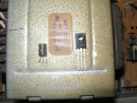
I replaced the transistors and resistors to the service bulletins specifications except I used 1381/3503 instead of 1370/3467, now I am not getting any signal through either channels. The only thing I can think of is I put them in backwards. I went buy the datasheets to make sure I put them in correctly.
I attached a photo of the old 3467 next to new 3503. With the flat side if 3467 touching the transformer the emitter is on the left? For the 3503 the three indents/circles facing up the emitter is on the left?
http://www.classiccmp.org/rtellason/transdata/2sa1370.pdf
http://www.fairchildsemi.com/ds/KS/KSA1381.pdf
Attachments
As you look at the face (lettering) both are ECB.
So I did put them in backwards. Any issues if I reuse them or could they have been damaged?
Why on the Sanyo datasheet do they have the transistor leads marked BCE looking at the lettering (this is what confused me and caused me to install these backwards)?
If you rotate the Sanyo picture around so the leads are down and the flat side facing you it will be ECB. You are not the first or last to be confused. Almost always the TO-126 package will ECB, can't recall it not ECB. The TO-92s are the ones to be careful with as far as pin outs go.
Craig
Check them with your DMM to see if they're hosed or not.
Craig
Check them with your DMM to see if they're hosed or not.
I bought extras and had enough to just replace them all even though they tested fine with my meter I don't feel like messing with it. Everything up and running now.
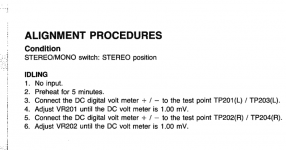
I don't get the alignment procedure (see attachment) 😕
I put my digital meter's test leads + on TP201 and - on TP203 and it reads 0mV
Turning VR201 does nothing...the meter still reads 0mV
Same results for the other channel.
Am I missing something here?
I don't get the alignment procedure (see attachment) 😕
I put my digital meter's test leads + on TP201 and - on TP203 and it reads 0mV
Turning VR201 does nothing...the meter still reads 0mV
Same results for the other channel.
Am I missing something here?
Attachments
Even though you figured it out this is what I do when it comes to doing the alignments. The first thing is to check what the SM tells you to do and compare it with the schematic, does it jive? Then do the math, E/R=I, does that jive. The early Marantz 22xx receiver SMs are notorious for errors, updates, etc. The idle current can be measured across one emitter resistor, two emitter resistors or even pulling a rail fuse and measuring the idle current thru the whole channel.
Craig
Craig
A little background info here so bare with me.
I got into this hobby because I am a guitar player and learned how to fix my own gear because it interests me. I have a copy of the The Art of Electronics and am very familiar with the first chapter (basic stuff) so I get all the basic equations like I=V/R. All of my gear and most of the people I know who play guitar use tube based amplifiers which is ancient technology and for me easer to understand. Over the years I have found myself becoming very familiar with the topologies of tube based gear and can easily understand what I am looking at. I have read chapter 2 which is transistors in The Art of Electronics and that is currently where I stand. So my knowledge on solid state topologies is very limited......especially with this amp, I looked at the schematic today for like 3 hours but I have to inch my way through it and I still don't fully see what is going on. In time I hope I am as smart as you where I can just look at modern SS gear and see the big picture of what its happening but until then I am very limited on my knowledge. Sorry for being such a noob......and I do appreciate all the help.
What I am trying to say is that I can measure the voltage drop across the emitter resistors and determine the current but I do not know what to make of this data. I get really down on myself for not being able to understand this stuff as well as I would like to but hopefully it clicks someday.
So I had some time to look at the schematic again and I am still really not to sure what to be looking for. Is the alignment procedure in the service manual given for this model not correct? I set it to 1mA like the manual says but if the manual is wrong then I would like learn the proper way of doing it. There is no rail fuse so I can't pull it and put my meter in series to read current draw.
Since the repair and service bulletin have been done I have been listening to it for a couple of days and it sounds good to me.
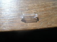
So other than maybe a little more tweaking (only if the service manual alignment procedure is wrong) the only other thing I would like to do is get the front panel meter lights working......but I can't find these lamps that have solder leads. They are 12v 150mA run in series from a 24v supply. I attached a photo of what they look like, any ideas where to find them?
Thanks
Since the repair and service bulletin have been done I have been listening to it for a couple of days and it sounds good to me.
So other than maybe a little more tweaking (only if the service manual alignment procedure is wrong) the only other thing I would like to do is get the front panel meter lights working......but I can't find these lamps that have solder leads. They are 12v 150mA run in series from a 24v supply. I attached a photo of what they look like, any ideas where to find them?
Thanks
Attachments
If you have 1mv across the test points and it's adjustable you should be OK. 1mv across .1 Ohms (2 x .05 Ohms) is 10ma, that looks OK.
Craig
I usually convert to LEDs when they come in with bad meter lamps.
Craig
I usually convert to LEDs when they come in with bad meter lamps.
Last edited:
If you have 1mv across the test points and it's adjustable you should be OK. 1mv across .1 Ohms (2 x .05 Ohms) is 10ma, that looks OK.
So I see that the test points 201 and 203 reads the voltage difference between Q217 emitter and Q219 emitter.....is the 10mA the combined current of Q217 and Q219 or the combined current of Q217, Q219, Q225, and Q227?
I usually convert to LEDs when they come in with bad meter lamps.
This is a great idea but does the meter dimmer still work with LED's?
You are measuring and setting the current thru the output transistors only, Q217, 219 and Q218, 220. Qs 221-228 are the commutator transistors that only come into play at higher power levels, so they are not conducting at bias setting time.
Yes the dimmer will still work. If you measure the voltage at the emitter of Q451 at max brightness that will give you the starting point to figure out the series resistor you'll need to add.
Let's say it's 20VDC and the LEDs draw 20ma and drop 3 volts each. Since they in series the current stays the same, 20ma but the drops add so we have 6 volts dropped across the LEDS at 20ma, so 6/.02 is 300. You would need to install at least a 300 Ohm resistor in series with the LEDs. That would be full brightness on that particular LED, a larger resistor would dim it down, that's an area you might need to experiment with to get the desired effect.
The Shack should have all you need to complete the conversion.
Craig
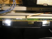
So a quick trip to Rat Shack and got a couple of white LED's, FW current 25mA, FW voltage 3.3v
I removed the old bulb holders from the pcb and cut the supply trace on the back of the pcb leading to the first bulb. Then I soldered in series a 470R resistor on the back of the board putting the resistor in series with the supply. Then I soldered the LED's where the bulbs once resided and presto.
With a supply voltage of 23v the drop across the 470R resistor is 16.4v or 23(supply)-6.6(forward voltage)=16.4
16.4/470=.035 or 35mA
.035x16.4=.57watts
I used a 2 watt metal oxide flame proof resistor but the resistor is a little warm to the touch......I can hold my finger on it for 3-5 seconds and that's about it. Is my math correct? Will 2 watts be enough? With the dimmer lower it's obviously much better. At the dimmers lowest setting I get 3.5v across the resistor.
I paralleled the 470R resistor with another 470R resistor and didn't really notice much of a difference in brightness so I think I will just stay with the 470R value.
Attachments
23-6.6=16.4
16.4/.025=656 Ohms
I'd put your 470 Ohm resistors in series for 940 Ohms. The resistors will be dissipating a little over a 1/4 Watt.
Craig
The resistor is to limit current, paralleled 470s (235) is too much current for the LEDs.
16.4/.025=656 Ohms
I'd put your 470 Ohm resistors in series for 940 Ohms. The resistors will be dissipating a little over a 1/4 Watt.
Craig
The resistor is to limit current, paralleled 470s (235) is too much current for the LEDs.
Last edited:
The LEDs are rated at 25ma according to your post, that's max current. You can play with the resistor values as long as you heed the max current.
Craig
Craig
The LEDs are rated at 25ma according to your post, that's max current. You can play with the resistor values as long as you heed the max current.
Thank you for clarifying, I don't know why I was thinking it was minimum current to get them to work.
I have since installed the two 470R in series and works great

Thanks
- Home
- Amplifiers
- Solid State
- Carver TFM-25 help