Chris,
Thanks for responding to my post. Unfortunately, I have no good means to check that tranny. My system is bi-amped and my Carver TFM's have the round wiper type vu meters (no led clipping indicators) but I never hear any distortion, metallic sounding treble or signs of clipping. The amp pushing the electrostats does run slightly warmer than the amp pushing the woofers but, you know, these magnetic field amps never seem to get actually hot like conventional amps. Electrostats are large capacitors (nasty load) and their impedence falls with increasing frequency. I have a 1 ohm resistor between the amp and tranny but I'm still leary of smoking the amp because the impedence probably falls below 2 ohms in the upper octave. Also, I have my EQ applying 10db of boost above 10khz to offset the anemic HF response... which likely puts significanly more strain on the amp (pushing ever more energy into falling impedence). My current esl tranny has 100:1 windings; which gives great LF extension and spl /efficiency but I've read that ratios above 50:1 tend to roll off the treble (except with very highest grade trannys) so that may be the whole problem. Since I am bi-amping with 380 hz X-over point, I don't need the higher turns ratio anyway. I've decided to upgrade to a dual 6v/230v toroidal tranny setup that will sum to about a 68:1 step-up. I've read that toroids give better treble response for given turns ratios and I'm looking for a deal on some now. Anyway, that's my plan.
Charlie
Hi John,
The first thing to do is to discharge all the filter capacitors, then reconnect the traces. I really hate when people start cutting traces, that is just plain stupid! Run around the board with your meter on "diode test" and check all the diodes. Go brain dead and check them all. List what is good, bad or missing as you go. You will be compiling a list of facts. After that, go ahead and test all the transistors as dual diodes. Again, list everything you find.
Now, can you please let me know what you have in the way of test equipment and what type of soldering station you have? You need to have the basics at least before you start. You will also need a variac (variable AC transfomer). There are some tests we can do at reduced power.
I don't have the service manual for that one any more. Is it possible to have it scanned so I can help you out in detail? My "large email" account is : bhomester at gmail dot com. Scan at the highest resolution you can please, 600 x 600 if possible (I don't need any higher), using a gray scale instead of black and white for the PCB layout and exploded chassis views. Schematics should be fine as B&W at that same resolution. Alternatively, an internet file sharing service may work.
-Chris
Hi Charlie,
-Chris
Okay then, do you meters show normal readings with the music, or do they tend to jump high when listening to normal levels. I would not expect to hear any clipping or "metallic sounding treble". An amplifier in distress when driving high notes may not sound much differnt in the high ranges.my Carver TFM's have the round wiper type vu meters
That may or may not be an issue. Your first tier commutators may be "sticking" on. You would need to use an oscilloscope to see that.The amp pushing the electrostats does run slightly warmer than the amp pushing the woofers
Shades of Bose 901 EQs, but not as bad. Yes, you may be making things worse there for the amp. That just can not sound good.I have my EQ applying 10db of boost above 10khz to offset the anemic HF response... which likely puts significanly more strain on the amp
Possible. Maybe some other member can help out here? I don't like electrostatics for the simple reason they are finicky about room position, more so than most boxed speakers. So, I can not give you any intelligent advice where these speakers are involved.I've read that ratios above 50:1 tend to roll off the treble (except with very highest grade trannys) so that may be the whole problem.
You seem to be approaching this in a reasonable manner. I'd suggest popping into the ESL speaker forum before you do anything else. There are some pretty sharp people in there. Just hold off spending any more money until you have this figured out some more. Post here when you have your answers please.I've read that toroids give better treble response for given turns ratios and I'm looking for a deal on some now. Anyway, that's my plan.
-Chris
Hi Chris,
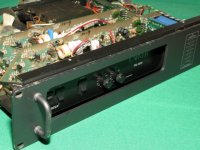
Absolutely. I intend pulling the thing apart and going over it with a fine comb. I hope it can be salvaged, most parts look fairly common. I have sent you some photos of the damage so you can get an idea. What power does the variac need to handle? I can step the voltage down further and limit the current with a 120V transformer if that would assist. I won't be powering it up just yet though....
Thanks for your help and interest! 😉
Cheers,
John
Hi John,
I normally use a 2 amp variac for this work, which would be a 1 amp model for the same power. I would rather use about a 4 ~ 5 amp model though (my mains voltage, yours would be 2 amp). You will only run to a maximum of about 80 VAC primary, above this the current draw becomes excessive normally, that's 40 VAC maximum for the 120 VAC market. You do this with the triac shorted, so you start getting power right away and you can catch high current draw before any other issues develop. You are also defeating the protection circuits. If you want, power up the +/- op amp supplies with another DC supply first, then the amp will pass signal as well. I suggest you wrap tape around the AC plug so that there is no way to accidentally plug into your mains with the triac shorted. Now that would be both unfortunate and spectacular!
I test all power amplifiers at reduced voltages when I am trouble shooting. This is very important just after you have worked on the amplifier. In general, a very good idea and it saves parts.
-Chris
Edit: John, YGM
Hi Chris,
I certainly appreciate all your advice and the time you have taken to help me out. I have removed both amp boards and partially dislodged the power board to check the caps - so far so good.
When I finish I would like to replace the 6A diodes and check the power supply out first, just in case there are any nasty surprises there. I think the fault originated on the 36 volt rail someplace. Pitty C24 and 4 of the diodes are missing, perhaps they would have told us more about the origin of the fault.
As a point of interest and to share my impressions, I have found at least 3 dry joints. I don't think these had a direct hand in the fault, but the assembly and construction technique could be better for a top shelf amplifier like this. Perhaps the tech who worked on it went looking for a fault caused by the poor soldering and blew the rest up while poking around.
I picked up this PM-1200 for the equivalent of about $80US so I think it deserves a reasonable investment in time and spares if there is a chance to get it going again.
It's certainly an interesting and educational experience for me!
Cheers,
John
Hi John,
I would have bought it without thinking twice. Nice score! You have a great deal of monetary headroom for this repair, and it is very well worth fixing.
Keep in mind that the sound quality kept improving as the newer models were made. So you are ahead of the game all ready.
-Chris
Wouldn't be the first time, or the last.Perhaps the tech who worked on it went looking for a fault caused by the poor soldering and blew the rest up while poking around.
The realities of automated assembly and low paid workers. Expect this type of problem with any product. Often you will see that larger objects with higher mass will suffer from bad connections. Two problems occur. One, the thermal mass is higher, so that these connections are made at a lower temperature than normal components. Secondly, these heavier items tend to move or vibrate some unless more extreme measures are taken to secure them during soldering. In any case, poor solder connections are a normal outcome with most products, not just Carver.As a point of interest and to share my impressions, I have found at least 3 dry joints. I don't think these had a direct hand in the fault, but the assembly and construction technique could be better for a top shelf amplifier like this.
Deal!!I picked up this PM-1200 for the equivalent of about $80US
I would have bought it without thinking twice. Nice score! You have a great deal of monetary headroom for this repair, and it is very well worth fixing.
Keep in mind that the sound quality kept improving as the newer models were made. So you are ahead of the game all ready.
-Chris
Hi Chris,
Yes, someone did not treat this with respect I guess. I'd want to use a little more caution poking around unfamiliar circuitry - but there you go. Since I picked it up as a 'junker' I don't have much to lose and a lot to learn 😉
I thought I would try my first attachment.... for others in the forum who would like to see what we have been talking about.
Cheers,
John
Attachments
I forgot to mention... a check of the output transistors shows what happens when things go wrong.... This is a list of Q1-10 and their state. (MJ15024's and MJ15025's)
Not a pretty
Q-------- Front------- Rear
1 --------- ok----------- ok
2 --------- ok----------- short
3 --------- ok ----------- ok
4 --------- ok ----------- open
5 --------- short ------- open
6 --------- open -------- short
7 --------- open -------- open
8 --------- ok ------------ ok
9 --------- ok ------------ ok
10 -------- short ------- short
Cheers,
John
Hi John,
Okay, good. A "damage" map is an excellent way to start servicing larger problems. Start by using the parts locater, then translate that to a schematic. Then you will have a clear idea what happened and what else may be damaged. I follow this exact procedure when I service a blown amplifier and I have the service information.
Since you own this amplifier, it is well worth it for you to buy a service manual. A clean PDF or an original manual is way better than a photocopy. A poor copy or PDF is a total waste of money. If I had the information, I would have gladly sent it to you. Perhaps another member can help here?
-Chris
Hi Chris,
I think I have resolved most of the issues up to now. (It looks like the PM-1.5 schematic is correct for the power supply of the 1200)
If you can point me toward the procedure for variac testing, I'll replace the components on the supply board and test. I assume that by using the variac to limit supply below 80V and shorting the triac, I should be able to check out the rail voltages without the amp boards connected. Some way to assure the triac is being controlled properly once the boards are in place?
Once I know the supply is going, I'll replace the components on the amp boards over the next couple of weeks as I order the parts (Q18, Q19, Q23 as well as those mentioned earlier)
Thanks for your help! I know you are busy so I won't keep pestering you (unless I get into trouble) 😀 😀
😀 😀
Cheers,
John
I think I have resolved most of the issues up to now. (It looks like the PM-1.5 schematic is correct for the power supply of the 1200)
If you can point me toward the procedure for variac testing, I'll replace the components on the supply board and test. I assume that by using the variac to limit supply below 80V and shorting the triac, I should be able to check out the rail voltages without the amp boards connected. Some way to assure the triac is being controlled properly once the boards are in place?
Once I know the supply is going, I'll replace the components on the amp boards over the next couple of weeks as I order the parts (Q18, Q19, Q23 as well as those mentioned earlier)
Thanks for your help! I know you are busy so I won't keep pestering you (unless I get into trouble)
😀 😀 Cheers,
John
Hi John,
I have never attempted to run the power supply with no amplifier cards installed. I guess you could try and run it up to 40 VAC input. Then just check that the ratios on your rails are about right, also check for ripple on your filter capacitors. Otherwise, you may get some odd behavior without the amps installed.
There is no real way to test the triac unless you set up a test jig, or load the supplies in the amp somehow. With no current draw, I would expect some very uneven firing and poor regulation. Once you provide some loading, you might try a light bulb in series with the AC power supply to the amp when you try it out.
-Chris
Yes, I had a look at what you sent and basically forgot to reply - sorry about that. Had a rough couple days.(It looks like the PM-1.5 schematic is correct for the power supply of the 1200)
I have never attempted to run the power supply with no amplifier cards installed. I guess you could try and run it up to 40 VAC input. Then just check that the ratios on your rails are about right, also check for ripple on your filter capacitors. Otherwise, you may get some odd behavior without the amps installed.
There is no real way to test the triac unless you set up a test jig, or load the supplies in the amp somehow. With no current draw, I would expect some very uneven firing and poor regulation. Once you provide some loading, you might try a light bulb in series with the AC power supply to the amp when you try it out.
-Chris
Carver redux
Good to know B.C. still generates interest--like this very informative
and loooong string. My The Carver Receiver 130 was DOA the first time
I tried to use it ($39 ebay) passing audio just fine but all inputs and radio produced un-godly HUMM. Thought o.k., lifted ground somewhere
or bad power sup cap, and since it was the studio newby, i just shelved
it. Cut to last week. no work to speak of, so I put it on the bench, open
the beast, and hook up to Auratones. Works perfect! all ins quiet and
put yer finger on the FM antenna lug and hear the local pbs station
loud and clear. Well it wouldn't be the first time audio gear 'fixed' itself.
All you techies have had the experience of of something like this, when
you blow your nose, or take a sip of coffee and the thing breaks, or
fires up again, take your pick. So I happily connect up everything to
my main sys, turn it on...HUMMMMM...Arggh! This time I trace/plug/
unplug everything one at a time-phono-tape deck-mixer-sound card all
just fine, the last thing: FM antenna ( an outside Y on the roof) and
there is that HUMMM...and it infects all ins with same noise!! Is this
a Carver Mag Res Pwr Sup anomaly?? Anyway, I strung some wire to
a small idoor type wishbone, and ran it to hang by the window and
the bottom line is this amp is a serious contender!
The Revelation: I have a set of Tannoy Gold 15's in the "Lancaster"
cabinets and since they're floor units in a crowded recording studio
I never paid much attention to amping them with the good stuff.
The wall monitors (Toa 15's) get the hot- rod tube amp, and a 20wt
Sony receiver did the Tannoys, which sounded totally mediocre.
You know what's coming next, right? Yep, ran the newly remastered
Beggar's Banquet SACD to the Carver to Tannoys and NOW I know
why the blessed things sell for thousands . Bloody Fabulous! You
must crank the Carver to loud! to get Tannoys to come alive and
then the DETAIL is a bit breathtaking.."Fast" and "No Smear"
are real terms for this amp. Admittedly Pop music of this kind is
relatively simple in spectrum and content, but I've heard SO many
expensive modern systems that don't get it this good.
Going thru my vinyl now, Pretenders #1and 2 boggle the senses!
Hi hasya108,
What you probably have there is a ground loop. There are some 75 Ω to 75 Ω isolation transformers you can buy. Stick one in series with your antenna line into the receiver.
A ground loop will magnify all ground currents. So while it will sound like the power supply inside your MXR-130, the supply sounds like it's fine.
Note too, some Carver receivers do pickup noise from their internal front panel displays. Rerouting some of the wiring will solve this. You need to remove the tie wraps and just start moving wires away from the bundle one by one. At some point you will have the display wires away from the wires that carry audio. Retie them with new plastic tie wraps, not too hard! Just arrange them apart as best you can.
Don't touch anything in there! Your supply voltages will be close to +/- 100 VDC. Touching the wrong thing will wake you up. For safety reasons, I would recommend you use a Carver technician for this job. There was a printed bulletin on this, he may have it.
-Chris
Nope.Is this a Carver Mag Res Pwr Sup anomaly??
What you probably have there is a ground loop. There are some 75 Ω to 75 Ω isolation transformers you can buy. Stick one in series with your antenna line into the receiver.
A ground loop will magnify all ground currents. So while it will sound like the power supply inside your MXR-130, the supply sounds like it's fine.
Note too, some Carver receivers do pickup noise from their internal front panel displays. Rerouting some of the wiring will solve this. You need to remove the tie wraps and just start moving wires away from the bundle one by one. At some point you will have the display wires away from the wires that carry audio. Retie them with new plastic tie wraps, not too hard! Just arrange them apart as best you can.
Don't touch anything in there! Your supply voltages will be close to +/- 100 VDC. Touching the wrong thing will wake you up. For safety reasons, I would recommend you use a Carver technician for this job. There was a printed bulletin on this, he may have it.
-Chris
Saturable reactor in audio amplification
Not in this case (of Carver's amplifiers), but yes it is possible.With a name like that I have visions of a saturable reactor being used as the amplifying device. Am I correct?
I got one of these amps that shuts down after awhile and start cycling then will start working again after a few minutes anyone know what could be wrong
I got one of these amps that shuts down after awhile and start cycling then will start working again after a few minutes anyone know what could be wrong
Carvers have over-current and thermal protective circuitry that will cause the symptoms you described when a fault is detected. I'm not qualified to advise you but there are some very capable tech types on the CarverSite forum that will jump in and help if you ask. They also have service manual for most Carver amps available as a freebie download: http://thecarversite.com/
good luck with it!
Chris-
Can you refer a U.S. service individual or company? Need work om power supply to eliminate 60hz hum in speakers. (I isolated the problem to the amp; it's not a ground loop issue with other electronics etc.)
Thanks
Can you refer a U.S. service individual or company? Need work om power supply to eliminate 60hz hum in speakers. (I isolated the problem to the amp; it's not a ground loop issue with other electronics etc.)
Thanks
I just got my TFM-45 back from Roland at Carver Repair in Oregon. Even Bob Carver now recommeds Roland as the top guy for his gear. He totally rebuilt my TFM and it really sounds great.
Carver Audio Repair
.
Carver Audio Repair
.
I did some research on the magnetic field calim years ago. basically it is a smart way of building a transformer by separating the zero load and full load design requirements. it has the core area for the power but lacks the number of windings for zero load. the primary would saturate the core at half the ac supply voltage. that's where the triac comes in.
so the transformer is designed with minimal window area, and the core is a huge stack of small EI laminates, with a small magnetic path length. wonder why not everybody is designing high power low weigth transformers this way. the coil formers are not standard though..
so the transformer is designed with minimal window area, and the core is a huge stack of small EI laminates, with a small magnetic path length. wonder why not everybody is designing high power low weigth transformers this way. the coil formers are not standard though..
- Home
- General Interest
- Everything Else
- Carver Magnetic Field Power Amp -whazzit????