One could do that, and it might be valid under set test conditions such as constant level (as is customary practice). But it doesn't necessarily describe RLT properly, unless one understands what it truly depends upon.... I would expect RLT to be specified as a function of frequency [RLT = f(ω)] though not amplitude, with the function taking a form derived from measurements of the cartridge in question.
For example, some magnetic loss mechanisms depend upon flux change slew rate. Your description RLT = f(ω) could fit for constant level sine waves. However, RLT = f(level) could equally fit in that example, for constant frequency sine waves.
RLT is a placeholder for non-linear loss mechanisms, a simplification that's OK-ish for set conditions. But the devil's in the detail, and expansion of RLT to understand and express its dependencies properly.
Personally, I surmise there two main aspects to non-linear coil behaviour: losses, and deviations from ideal inductance/transfer function. RLT is devised in a simple way under set conditions to express losses, but not inductive changes.
LD
Last edited:
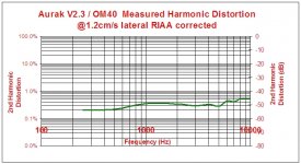
Thanks, davidsrsb, that's interesting. The discrepancy is about 25% at 6kHz, as per fig 3. Hysterisis losses rising.Coercitivity increases with frequency
https://lib.dr.iastate.edu/cgi/viewcontent.cgi?article=1170&context=ameslab_pubs
LD
More data. Losses depend on both frequency and level, but the relationship is somewhere between f and f2 and the Flux level loss is close to SQRT(Flux)
https://www.mag-inc.com/Media/Magne...e/2016-Magnetics-Tape-Wound-Cores-Catalog.pdf
https://www.mag-inc.com/Media/Magne...e/2016-Magnetics-Tape-Wound-Cores-Catalog.pdf
Whose definition of resistance?jaddie said:Yes, there is one big reason. By definition, resistance cannot vary with frequency. If it does, it is not pure resistance, and would exhibit a reactive component. If it varies with level, it is not pure resistance either, but rather a nonlinear component (like a diode, for example).
Consider a piece of wire, forming part of a circuit. It has inductance, resistance and capacitance. The inductance and capacitance are approximately independent of frequency, although the corresponding reactances vary in the usual way. The resistance increases with frequency due to skin effect, varying like square root of frequency. Are you saying that this is not real resistance but some side effect of reactance? If so, you may need to ask the electromagnetism textbook authors to rewrite their creations.
I think the needle tracks especially well the high frequency content since the rotation speed and the frequency of say 5khz is very high vs the time it takes to smear the sound.
Depends on the tracking level, yes, many FF or FFF sounds are only distortion on a turntable. however many cartridges have under 0.1% thd at like 6khz.
Depends on the tracking level, yes, many FF or FFF sounds are only distortion on a turntable. however many cartridges have under 0.1% thd at like 6khz.
however many cartridges have under 0.1% thd at like 6khz.
Please show me one or for that matter something to verify actual vinyl playback of that.
I understand non-linear systems. I'm asking for at least some metric re: how "non-linear" it is.
Actual LP tracing very, one can easily see it by eye on a scope. 1-3% often so assuming soft low order non-linearity the amplitude variation of the fundamental could be +-1dB or so with level even with a perfect motor assembly. I don't know the level of effects they are looking for.
EDIT - Sorry on the skin depth read my gauge table wrong (mm vs mils).
Last edited:
This is the best I have seen to date. Courtesy of LD
THD at 5cm I would assume to be much worse?
I would assume same too. Not seen a measurement I trust as Paul Miller's ask more questions than they answer.
Can't see anything in the pic, resolution is too low. But impedance measurements are a fraction of the total system, don't begin to tell the whole story, and by themselves might prove misleading.Some measurements on cartridges (one channel) with an LCR meter (DER EE model DE-5000)
George
Whose definition of resistance?
Consider a piece of wire, forming part of a circuit. It has inductance, resistance and capacitance. The inductance and capacitance are approximately independent of frequency, although the corresponding reactances vary in the usual way. The resistance increases with frequency due to skin effect, varying like square root of frequency. Are you saying that this is not real resistance but some side effect of reactance? If so, you may need to ask the electromagnetism textbook authors to rewrite their creations.
We need to drop the discussion of skin effect because it doesn't apply in the case of wire used in cartridges and audio frequencies carried by them. Skin depth is a function of frequency, but when the wire diameter is equal to, or less than the skin depth at any frequency of concern, there is no skin effect. The skin effect is a pronounced differential of apparent resistance that becomes significant only when skin depth reduces the effective cross sectional area of the conductor.
Clearly, there are mechanisms that could change a resistive component with frequency, but the real question is, based on the cartridge equivalent circuit, how much does the total system response change with RLT changing with frequency, and more important to this discussion, how much does the total system frequency response change with level? We might be getting closer to defining a possible cause, but there are still no quantified values here relating to the possible magnitude of the effect.
My concern is that much is being made of the variation of cartridge impedance with frequency (or possibly level), but we don't have a resulting FR delta of the total system. And, without taking the entire system (from Holman's paper: cartridge response, two forms of inductance interaction, the amplifier’s open-loop gain, bandwidth, and input impedance; the RIAA feedback loop; and the cartridge)into account for analysis (or measurement), we have neither predicted nor quantified the resulting changes caused by varying any one element in the cartridge equivalent circuit, much less several.
More interesting (though still not definitive) would be THD vs Frequency vs Level. Anybody have that data?
Can't see anything in the pic, resolution is too low. But impedance measurements are a fraction of the total system, don't begin to tell the whole story, and by themselves might prove misleading.
jaddie
Left click over the attachment.
Then Left click on the lower left corner over the X rectangle.
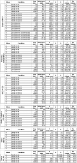
The LCR measurements is one set of data.
Cartridge Impedance plots will come later. It's another set of data (and a lot of it).
We'll see which of those are useful and which are not. Maybe all is useless.
After that, suggestions will help to do other tests.
I can't help it if you are in a hurry. I have only so much time.
George
Could you emulate the moving part with a small coil of wire to drive a magnetic field? It won't model the mechanical but it could show the magnetic electric interactions.
It was the example that came to mind when you said that, by definition, resistance does not change with frequency. One counter-example is enough to disprove a potential theorem.jaddie said:We need to drop the discussion of skin effect because it doesn't apply in the case of wire used in cartridges and audio frequencies carried by them.
No. The skin effect is a pronounced differential of actual resistance.The skin effect is a pronounced differential of apparent resistance
Thank you. That is what I was trying to establish.Clearly, there are mechanisms that could change a resistive component with frequency
The bigger fish are already frying...
All right. Trust your nose.
Never said that cart impedance is the only or the main issue on cart dynamic behavior. Work on searching for other variables can and has to progress .
I am not trying to steer the conversation toward impedance. But I am a bit thick and I need time to grasp things. Cartridge impedance will be my toy for a while.
You mentioned distortion vs signal level. Distortion increases with level, evident on single tone test tracks playback.
Note, this varies with the system and adjustment level. (attachements are from the same system at different adjustment points)
I think there are good indications that increased distortion increases loudness thus perception of dynamics.
Demian, the second coil on a stereo cartridge can be used as such an extra coil, no?Could you emulate the moving part with a small coil of wire to drive a magnetic field? It won't model the mechanical but it could show the magnetic electric interactions.
Reciprocity older posts. Start from here. Aug 7, 2015, to Aug 8, 9,10, 12. Then Nov 2,3.
John Curl's Blowtorch preamplifier part II
George
Attachments
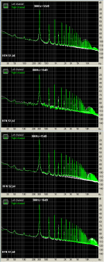
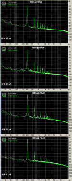

Yes, increased distortion changes perceived loudness, but to couple that with the perception of dynamics is a very slippery slope. Generally, distortion caused by nonlinearity reduces the perception of dynamics, often in a very pronounced way. It's a tool used in loudness war processing, for example.You mentioned distortion vs signal level. Distortion increases with level, evident on single tone test tracks playback.
Note, this varies with the system and adjustment level. (attachements are from the same system at different adjustment points)
I think there are good indications that increased distortion increases loudness thus perception of dynamics.
Demian, the second coil on a stereo cartridge can be used as such an extra coil, no?
George
Not well with over 30 dB of isolation/cancellation between channels. What you want to explore is the mag field interactions. A single turn with a constant current will show a lot about both frequency vs. sensitivity and level vs. saturation. Possibly a 1/2 turn of very fine wire would do the job.
- Status
- Not open for further replies.
- Home
- Source & Line
- Analogue Source
- Cartridge dynamic behaviour