Interesting, however I am surprised the second arm could pick up the resonance in the disk which would be obviously 99% directed to the clamp and platter
There is nothing to base that number on, it is a matter of mechanical impedance matching, coupling, loses, etc. Less than 100% is all one could say.
Part of the challenge in examining coil behaviour at true signal levels is synthesising signals small enough, and being able to measure impedance with enough resolution using only that signal for the method to be practicable and meaningful.
Over the years I've occasionally thought about this problem, and didn't come up with an answer so parked it.
I thought about a test where a very small coil is placed in location to replace the stylus armature ? Then that coil be used as a primary in conjunction with the cartridge coil as a secondary effectively as a transformer?
Or to somehow add an overwinding to a cartridge coil, and characterise the core as a transformer ?
Or to leverage existing work characterising non-ideals of inductors with construction and cores of this type, for small signals, but couldn't find any prior at least a few years back.
LD
@Jaddie: try reading more than one paragraph of the interview before concluding things.
Any link to that interview?
George
Jaddie your conclusion is that the needle moves the air around it like a transducer. It is not how I perceive it. The needle acts like a string, 'attached between the surface and the pivot which acts like the bridge of a violin. There is another portion of the sound coming from the scratching on the groove.
It is like a very complicated violin string with many twists, knots, lengths.
It is like a very complicated violin string with many twists, knots, lengths.
Cantilever transmits mechanical vibration to the cartridge body through the lossy elastic suspension. The cartridge body transmits vibrations to the tone arm. Tone arm to the arm board.
Therefore depending of the degree and kind of decoupling between all these, the cantilever’s fulcrum vibrates destroying the idea of fixed reference point.
There goes all the stories and sweat about moding cartridge bodies, decoupling scenarios ect.
(is all this relevant to the subject of this thread?)
George
Part of the challenge
I can’t understand what is the purpose of the extra coil .
Lucky, through REW you can record three kinds of sweep files (16bit/24kHz).
Freq to 24kHz, level from –3dBFS to –60dBFS (0dBFS in volts depends upon your soundcard). You can digitally attenuate these –60dBFS files still further to your liking.
If you have any difficulty, I can record and upload such files to your specs
George
Attachments

Thanks Bill.
Bong!
What can I do about it? (WinXp SP3, Google Chrome)
George
Bong!
What can I do about it? (WinXp SP3, Google Chrome)
This site can’t provide a secure connection
Home Page | Stereophile.com uses an unsupported protocol.
ERR_SSL_VERSION_OR_CIPHER_MISMATCH
The client and server don't support a common SSL protocol version or cipher suite. This is likely to be caused when the server needs RC4, which is no longer considered secure.
George
Or to leverage existing work characterising non-ideals of inductors with construction and cores of this type, for small signals, but couldn't find any prior at least a few years back.
LD
These guys make sensing coils for implantable medical devices (down to #60 wire!).
Ultra-Fine Wire Winding | Precision, Inc.
Sure, but it still doesn't matter. What you're hearing is energy that has already left the entire mechanism and become airborne.Jaddie your conclusion is that the needle moves the air around it like a transducer. It is not how I perceive it. The needle acts like a string, 'attached between the surface and the pivot which acts like the bridge of a violin. There is another portion of the sound coming from the scratching on the groove.
It is like a very complicated violin string with many twists, knots, lengths.
These guys make sensing coils for implantable medical devices (down to #60 wire!).
Plus they introduce angular winding.
George
I can quote the relevant paragraphs (google have been causing problems with cert blocking recently).Thanks Bill.
Bong!
What can I do about it? (WinXp SP3, Google Chrome)
George
There was an experiment which is relevant to all this. I was listening to a record via headphones, and then lowering a Watts Dustbug [record-cleaning brush] onto it. And you could hear modulation coming through. The stylus was running on a blank groove, while the Dustbug was on a heavily modulated groove—and you could hear that at a very low level from the pickup. In other words, although it was a very lightweight thing, not putting much energy back into the groove, there was no getting away from the fact that the groove is a plastic device, and if it's moving an object—a mass—some motion is going to be transmitted into the record material, laterally.
"This switched me on to the idea that if a Dustbug can do that, what is the pickup itself doing? So, naturally, I tried putting another pickup onto the record, and the amount of modulation that comes through is enormous—like a reverberant version of the original. Which makes you realize that this is happening all the time, whenever you are playing a record! Because of the mechanical impedance of the stylus, it is sending out information into the record material, which will come back to the tracing point and be heard. The logic of it is that the poorer the trackability of a pickup, the more energy is going to come back to it.
"As a further experiment, I borrowed a number of moving-coil pickups which required varying playing weights according to their compliance. Using a lightweight moving-magnet as a monitor, I found that the energy transmitted into the record—that you could listen to—was proportional, more or less, to the playing weight; that is, to the stiffness, or the high mechanical impedance, of the other pickup. Which made me suspect that a lot of the preference for moving-coils—the so-called wonderful reproduction of ambience and spaciousness of moving-coil pickups—is a load of hooey! You are reproducing the information being scattered around the record by the pickup coming back to itself. And these experiments seemed to confirm that.
"I've mentioned this several times in print, and it's not a very popular thought! I'm not saying that moving-coils aren't better in many other respects, which they may well be. Maybe they are more linear—all sorts of factors may come into it. But this was one of the things I was somewhat worried about, when I was concerned about reproducing LPs. I don't have any LPs now!"
Thank you Bill.
I wonder why he didn’t think of painting the record edge with a green felt pen instead of abandoning playing the vinyl.
😀
George
I wonder why he didn’t think of painting the record edge with a green felt pen instead of abandoning playing the vinyl.
😀
George
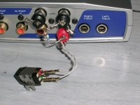
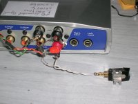
Tomorrow I will redo the test with shorter wires. I think that phase plot hints to high capacitance of the wiring.
There is only little betterment with the shorter cables.
With DUT like an MM cartridge, using a passive jig is problematic, as Rin of the soundcard (10kOhm) acts as a voltage divider when Z of the DUT goes above some kOhms at high frequencies.
I built a buffered Impedance measuring jig to get around this problem. Results are very good. I’ll post tommorow.
George
Attachments
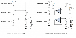
PC soundcard approaches will work. A large resistor in series with the source, eg 1MOhm will attenuate the measurement signal by over 60dB to mV levels. The voltage across the coil will need a simple opamp preamplifier of 20 to 40dB gain. you will need to put the jest jig in a metal box for shielding.Part of the challenge in examining coil behaviour at true signal levels is synthesising signals small enough, and being able to measure impedance with enough resolution using only that signal for the method to be practicable and meaningful......
LD
I read this with amusement. I've been drafting a reply post on and off all day, just haven't had time...and guess what? I quoted the same passages! Of course, I had them underlined and highlighted...but whatever.I can quote the relevant paragraphs (google have been causing problems with cert blocking recently).
I was also asked to read more than one paragraph before drawing conclusions, which I had, but had little time to elaborate. So, here's the elaboration, and my conclusions have not changed.
There are some pretty big issues here. First, like pretty much everything else around here (and I have to say, I am disappointed)...assumptions are being made, and conclusions are drawn without any supporting scientific data. The Crabbe Test is another one of those. We have absolutely zero data, and no information on how the test was made, or how he drew his conclusions. And from that, some have made further assumptions and drawn similar conclusions. Some might say, well I should read his original article. I'd love to. It's not available. If someone has it and can scan it, great. I seriously doubt any of the following issues will be satisfied by that article.
Here's what we know about the Crabbe Test, and how it came about:
1. He found he could "hear" the DustBug creating vibrations that traveled through the record to the pickup.
2. He found that vibrations of a stylus in a modulated groove could travel through the record and be picked up by a high compliance MM cart elsewhere on the record, presumably a silent groove.
3. He found that the intensity of the transmitted vibrations related inversely to the compliance of the playing cartridge, and directly to the tracking force of that cartridge
4. He concluded that, because another cartridge could pick up those vibrations, that they were also transmitted back to the originating cartridge, and would be combined into the electrical output.
What's missing is:
A. No measurement of the transmission characteristic of the record
B. No measurement of the temporal characteristics of the transmitted vibration through the record
C. No measurement of the return loss of the total path, play stylus back to play stylus
D. No measurement of the actual degree of contribution of the induced vibrations to the playback electrical signal.
The assumptions being made (incorrectly, and without data) are:
A. That the transmission characteristics of the record are very efficient
B. The transmitted vibration 'reverberates' (he used that word), implying a decay of 10's of milliseconds (just to qualify for the term)
C. The return loss is minimal, a pronounced amount of induced vibration is returned to the playing cartridge
D. The returned vibration is clearly audible, and detrimental in the electrical signal
Here are some of the problems with these assumptions:
Absent any transmission characteristic of the actual record, we know that the induced vibration of the record caused by the playback stylus must be significantly less than that of groove modulation. That's because of the way it is generated...by a low mass stylus being accelerated by a modulated groove. We also know that the record is at least partially damped by it's own weight on a platter, which would further attenuate record vibration. And we know that for vibration to be returned to the stylus it must impact a boundary, presumably the record surface or edge, and be reflected back to the stylus. Boundary reflections are by nature lossy, so the retuned vibration waves would be further attenuated. We also know that the speed of sound through a solid of any kind is far faster than the speed of sound through air, while the wavelengths in involved in audio are quite long, making the effect of any reflection and return virtually instantaneous, and therefore, in phase with the groove modulation.
We also know that Crabbe never tested the temporal nature of these vibrations because at the time this "work" was done there were no practical means to do so. So there's no confirmation that induced vibrations do, in fact, "reverberate" for 10's of milliseconds.
The question remains, what did Crabbe test, apart from detecting sympathetic vibrations with another cartridge? Well, we have no information on that.
What he did find is that high compliance, low force cartridges produced less vibration. No surprise there. Were damping devices tested? We don't have any information.
He seems to have drawn the conclusion that low compliance high force MC cartridges of the day produced less preferable sound. He seems to attribute induced record vibration and its reintroduction to the pickup as a detrimental part of the sound, but there are several thinks to note:
1. There was no way to isolate the variables of compliance/force and record vibration as they are related
2. There are other audible characteristics of low compliance/high for cartridges that strongly contribute to the resulting sound quality
3. The audible testing was fully sighted, and therefore, strongly biased
4. The observation that a second cartridge could pick up the vibrations caused by the first was forced to a conclusion that the first cartridge must be able to pick up it's own induced vibrations, when nothing of the kind was ever tested or proven. It could easily be shown with some impulse testing, even a tone burst or three, but nobody has bothered. Why, do you think?
So, here we are. He's been dead for 10 years, so we can't ask him. Until the original HiFi News article surfaces, we don't actually know what he wrote. We do know plenty about what he didn't do, though. He didn't perform complete, controlled, scientific tests, and didn't do anything in the time domain. Odd, given he was a radar guy!
And with today's high compliance cartridges with low tracking force, I simply cannot imagine why anyone thinks this is an issue. At all.
And what does any of this has anything whatsoever to do with cartridge dynamic behavior?
Apols I should have been clearer.PC soundcard approaches will work. A large resistor in series with the source, eg 1MOhm will attenuate the measurement signal by over 60dB to mV levels. The voltage across the coil will need a simple opamp preamplifier of 20 to 40dB gain. you will need to put the jest jig in a metal box for shielding.
The largest sine signal trackable at 10kHz works out about -60 dBV cartridge output level. So to explore the phenomenum at normal or small signals we need to generate accurate sine waves at low impedance perhaps around the -100dBV levels, and be able to measure them reasonably accurately. It's not impossible, but it's not trivial and is really an instrumentation job.
It's much tidier George's rig now, but I think not too surprising that flying cable strays don't factor. What I find more generally surprising is that self-capacitance of the coil doesn't show up as resonant system (with coil inductance) when looking at coil impedance..........?
I have a feeling of deja vu about this, did we examine self-resonance this way before and fail to find it? If so I wonder why......?
Attached is a table of commercial inductor parameters that shows highlighted similar type and construction as a cartridge coil, at face value.
LD
Attachments

Last edited:
@:Jaddie: So many negative words, so little contribution to the discussion. You are just wrecking the SNR of this thread. As such I am going to have to put you on ignore unless you can actually be postive. We have no idea who you are other than you popped up and are now p*ssing on this thread without helping. As such unless you get some kick from disrupting this thread you are wasting your time.
It's much tidier George's rig now, but I think not too surprising that flying cable strays don't factor. What I find more generally surprising is that self-capacitance of the coil doesn't show up as resonant system (with coil inductance) when looking at coil impedance..........?
I am working in collecting impedance data with the new jig. I am not ready yet.
But we know the dip is above 20kHz
mechanical resonance in MMs
I have a feeling of deja vu about this, did we examine self-resonance this way before and fail to find it? If so I wonder why......?
Deja vu?🙂
mechanical resonance in MMs
mechanical resonance in MMs
Attached is a table of commercial inductor parameters that shows highlighted similar type and construction as a cartridge coil, at face value.
I have a DER EE DE-5000 LCR meter. I’ll post such measurements too 100Hz, 120Hz, 1kHz, 10kHz, 100kHz (God permitting )
George
- Status
- Not open for further replies.
- Home
- Source & Line
- Analogue Source
- Cartridge dynamic behaviour