Thank you both. The long winded explanation of this stuff bit the dust in the great purge AFAIK. Go figure.This is what Bill had unearthed and posted in this forum(attachment).
The concept arose from the quest to eliminate cable C, and hence the LCR resonance, from MM/MI playback. Mostly as a means in itself to avoid the vagueries of MM/MI loading, but also to expose any mechanical resonance masked by LCR resonance and so understand more about vinyl playback.So far you’ve been cryptic on the “why” regarding the calculation details of your Aurak brainchild🙂
I'm not sure whether the idea emerged from the Barney, but I think Aurak came before I was aware. Certainly before I was aware of the 1981 patent which pretty much nails Aurak, including the 75uS pole conversion, but which has lapsed now.
As to methodology, it went something like:
1. Work out overall division of gain structure.
2. Design 1st stage 75uS conversion topology and choose standard E values that fit gain structure.
3. Notice the relationship that allows nL-R as a simplification to eliminate cartridge parameters from affecting component value choices.
4. Choose 2L-R as the illustration since it works for most carts. With hindsight 3L-R would be more universal.
5. Design the 2nd stage to implement remaining RIAA filter and set overall gain using standard E value parts.
6. Simulate, compensate for hf stability and build it.
7. Hope that real cartridges tolerate TI loading.
8. Listen, measure.
9. Put the screws in the case and enjoy it 4(?) years.
LD
Thanks Lucky.
As a character, I am very comfortable with item 9 above but at the same time I feel the inner need to kindly ask you to take a deep breath and dive into item 3 above
George
As a character, I am very comfortable with item 9 above but at the same time I feel the inner need to kindly ask you to take a deep breath and dive into item 3 above
George
If people can be patient for a few hours perhaps I could address that. I had a real mental block on it at first and Hans gave me a few pointers that made me realise how dumb I was being. As a result I can probably explain it in short words that all can understand 🙂
Thanks Lucky.
As a character, I am very comfortable with item 9 above but at the same time I feel the inner need to kindly ask you to take a deep breath and dive into item 3 above
George
George, funny I was wondering late last night about the confusion.
My take, LD can spank me if he wishes.
Take a typical MM cartridge with a series R and L feeding a TIA input, you have a pole at a frequency determined by L&R. The first stage is a high-shelf with a zero to cancel the input pole and a pole at 75us where you want it for every cartridge as well as a desired gain.
I think LD's procedure was based around making a universal first stage that would fit most cartridges with only a small R to pad the internal series R. that way one shelving circuit gets close for all. There are enough degrees of freedom to build the circuit around any cartridge but since all the values interact it is fairly tedious to get a set that uses standard E values. There is also the problem of changing all the values for every cartridge.
It should be obvious a different circuit for each and every cart has little commercial value and would appeal to only the most die hard DIY'ers. For decades folks have been publishing about getting absurd levels of adherence to the RIAA curve. It's become obvious to me this is a little silly. The pole/zero mismatch of the simplified approach is a very small blip.
As for high frequency stability, it's the standard TIA design procedure. The cable capacitance forms an extra input pole which interacts with the GBW product of the op-amp. There is an optimum small feedback cap that flattens the response, here a little overkill is probably OK.
Last edited:
@Scott
I will welcome the comments and in case there is something not correct, I can always add an erratum to everybodies satisfaction to the original message .
That prevents people reading this technical addendum in future, from getting confused.
You had two points: A) 4k2 being more exact and B) a change in overall gain when giving the two resistors that were calculated in parallel different values.
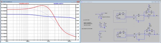
A) because your of comment that 4K2 is exact and 4K19 is slightly off, I have made a sim containing 3 parallel versions.
1) the exact version with a Laplace function having a 75usec pole,
2) The version with 180nF/420/5K4/4k2
3) The version calculated by me with 180nF/417/5k4/4k19
In the image below you can see the deviation from the exact curve for version 2) and 3).
Deviation for 2) is within 0.06dB and 3) within 0.01dB.
So both are excellent and more than good enough, but your comment does not feel as quite correct.
B) About the change in gain when dividing into different values is correct, but this lies within 0.1dB, completely insignificant to my opinion for a phono preamp.
But I will add this remark as an erratum to my original posting .
So it would be helpful if you could remove your posting in the addendum, to prevent people from getting confused from what's right and what's wrong.
Hans
To keep the technical addendum as pure as possible, it would be great if comments could be put here.Not exactly, the error is very small but the two resistors fall out of a quadratic equation 5.4K and 4.2K are exact and can be swapped but making them equal gives a slight gain error. You need to be careful any two resistors with the right parallel value definitely do not work without changing the gain which is proportional to the sum which you want to keep equal.
I will welcome the comments and in case there is something not correct, I can always add an erratum to everybodies satisfaction to the original message .
That prevents people reading this technical addendum in future, from getting confused.
You had two points: A) 4k2 being more exact and B) a change in overall gain when giving the two resistors that were calculated in parallel different values.
A) because your of comment that 4K2 is exact and 4K19 is slightly off, I have made a sim containing 3 parallel versions.
1) the exact version with a Laplace function having a 75usec pole,
2) The version with 180nF/420/5K4/4k2
3) The version calculated by me with 180nF/417/5k4/4k19
In the image below you can see the deviation from the exact curve for version 2) and 3).
Deviation for 2) is within 0.06dB and 3) within 0.01dB.
So both are excellent and more than good enough, but your comment does not feel as quite correct.
B) About the change in gain when dividing into different values is correct, but this lies within 0.1dB, completely insignificant to my opinion for a phono preamp.
But I will add this remark as an erratum to my original posting .
So it would be helpful if you could remove your posting in the addendum, to prevent people from getting confused from what's right and what's wrong.
Hans
Attachments
Hence my comment "close but not quite". As it's intended as a reference, might as well get it right I figure.
From your post, the part that needs correction is "One of the tools used for investigation has been the so called Aurak preamp that LD or Luckythedog brought forward. This a phono amp that goes one step further as replacing the 47k termination resistor by a much lower value of ca 10k creating a 75usec pole." In Aurak there is no ca. 10k series resistor creating the 75us pole - that topology is the Barney Oliver et al, definitely not Aurak.
I published a sketch once for an op-amp version of the Barney Oliver preamp, but never built it. It was called "The Barney".
LD
Ld,
I have made an erratum to my original posting, using the input that you gave. I hope this removes any possible misunderstanding for future readers.
For the same reason as I asked Scott, I think it's good to keep the technical addendum free from comments.
All comments given to me in this Cart. Dyn. Beh. thread will be added in the addendum as a correction in the form of an erratum to the original posting.
If you are not yet satified what's in the erratum Aurak, technical reference as addendum to Cart. Dyn. Behav.please let me know and I will take further action.
So my request is also to you is to remove your posting in the original addendum.
Hans
OK, but usually I charge...…...😉In fairness it's a good summary.My take, LD can spank me if he wishes.
But...…….
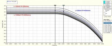
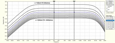
There's a trick: cartridge R can be arranged so that effect upon the natural LR time constant is compensated by tracking effect on the correcting shelving filter. See attached sims for L=100mH to L=1000mH and corresponding R=2L for both (a) the 1st stage only forming the 75uS time constant, and (b) the whole preamp. In this way, errors are very small over a wide range, such as a decade, of cartridge L. Given standard E values are used, it is remarkable really.I think LD's procedure was based around making a universal first stage that would fit most cartridges with only a small R to pad the internal series R. that way one shelving circuit gets close for all. The pole/zero mismatch of the simplified approach is a very small blip....
It's not a 'one size fits all' circuit, it accommodates cartridge L to null the natural pole. That's the spanky bit 😉
LD
Attachments
Last edited:
Just for a reference point from a man with some odd cartridges on 3L-R calculations. My lowest added resistance is 27Ohms and my highest is 1290Ohms. It serves me right.
Of course the shape of the curves don't change because Tc the time constant from Cart plus added R stays at 500usec for all shown combinations.There's a trick: cartridge R can be arranged so that effect upon the natural LR time constant is compensated by tracking effect on the correcting shelving filter. See attached sims for L=100mH to L=1000mH and corresponding R=2L for both (a) the 1st stage only forming the 75uS time constant, and (b) the whole preamp. In this way, errors are very small over a wide range, such as a decade, of cartridge L. Given standard E values are used, it is remarkable really.
It's not a 'one size fits all' circuit, it accommodates cartridge L to null the natural pole. That's the spanky bit 😉
LD
But I wouldn't be happy when changing a 100mH for a 1000mH Cart, overall gain would drop by 20dB, apart from the SNR that will also drop quite a bit. 😀
Hans
Which way does the gain change? Typically lower inductance goes along with lower cartridge output voltage..But I wouldn't be happy when changing a 100mH for a 1000mH Cart, overall gain would drop by 20dB, apart from the SNR that will also drop quite a bit. 😀
Hans
That may well be, but certainly by a factor 10.Which way does the gain change? Typically lower inductance goes along with lower cartridge output voltage
Hans
I must re-run my calculations as it seemed to be self correcting. In particular for series mono wiring the output level stays constant, which is handy. you must of course dummy load the other channel.
This should of course have been "certainly not by a factor 10".That may well be, but certainly by a factor 10.
Hans
Searching on the web I found this on the Audiogon site,
Moving coil cartridges usually have voltage output of less than 1.0 mV (although there are a few "high output" MC cartridges with output of 1.5 mV or so).
Moving magnet cartridges usually have output levels in the 3-6 mV range (although a few may run higher).Jul 27, 2003
This design is only for high output MCs and the various MM families.
There is no need for a low output version as they don't have audio range LC resonance and a low voltage noise transimpedance amplifier for <10 Ohm sources is a challenge
There is no need for a low output version as they don't have audio range LC resonance and a low voltage noise transimpedance amplifier for <10 Ohm sources is a challenge
My own fault again, but mine go from 1.8mV to 10mV(20mV in series mono, with a combination that is 0.9mV. I think that will cover most things 🙂. from the sums I have done the net voltage out of the amp is mostly the same.
Although thinking about voltage when we are in the current domain is odd.
Although thinking about voltage when we are in the current domain is odd.
We are a bit turning in circles.This design is only for high output MCs and the various MM families.
There is no need for a low output version as they don't have audio range LC resonance and a low voltage noise transimpedance amplifier for <10 Ohm sources is a challenge
I was referring to LD's image with coils from 0.1H to 1H where it could be seen in his posting that gain was dropping by 20dB when going from small to large inductance..
That's why I referred to an Audiogon message , telling that according to them most MM Carts are in the same 3-6mV range.
Hans
It's not a 'one size fits all' circuit, it accommodates cartridge L to null the natural pole. That's the spanky bit 😉
LD
Just my thought process, I would start with with how to use no R so the cart is connected directly to the TIA to absolutely maximize SNR. Just a prejudice. I also thought it would be nice to keep the gain at 20dB, that could be my lack of experience whit much of any output variation in carts.
Last edited:
So it would be helpful if you could remove your posting in the addendum, to prevent people from getting confused from what's right and what's wrong.
Hans
With two equal values for R3 and R4 they can each be 42K, or 47k + 38K or whatever gives 21k when paralleling.
This is wrong, 500K in parallel with whatever makes 21k is a very different result.
I said you can not use any two resistors with the same parallel value. I will not remove my post and you can carry on as you wish.
Last edited:
- Status
- Not open for further replies.
- Home
- Source & Line
- Analogue Source
- Cartridge dynamic behaviour