I connected a cable bridge across the speaker terminals (+ and -) of any channel, I get 0.000V without protection mode. If I connect a 4 ohm speaker, I get 0.003v without protection mode.
I disconnect the speaker or wire of the speaker terminals and returns to protect mode.
I disconnect the speaker or wire of the speaker terminals and returns to protect mode.
When you checked those two transistors, did you carefully check for leakage and open junctions as well as shorted junctions?
Hello
the two transistors are 2N5401. I checked and is correct. Not short nor leaked. when connected on the plate, not heated.
The only thing I have not seen clear is the hfe gain. According to datasheet, you must be between 60 and 240 HFE, and i get results 230-240 hfe, too close to the specifications limit.
Greetings.
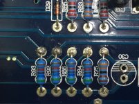
For the 4 resistors in line near the two 5401s, does one end of each connect to the emitters (or bridging speaker terminals) for each channel?
Yes, each resistor (R93, R92, R86, R84) have direct connection to the terminal + speaker. The resistor R75 has a direct connection to the GND speaker terminal.
The 5 resistors is a tested and work perfectly.
The 5 resistors is a tested and work perfectly.
Attachments
Last edited:
Desolder one leg of each of those resistors (R93, R92, R86, R84). With the two 5401s in the circuit, does the amp go into protect?
Are you saying that only one of the 4 resistors listed makes a difference or are you saying that lifting only one (any one) of the 4 will prevent the amp from going into protect?
Hi
Raising only one pin of one of the four resistors (any), prevents the amplifier from entering protection.
Raising only one pin of one of the four resistors (any), prevents the amplifier from entering protection.
With the 5401s out of the circuit, install the outputs for one channel and see if that channel will produce clean output.
You will need to very closely monitor the current draw and the temperature of all components that would normally be clamped to the heatsink (or clamp them down tightly).
Keep installing outputs, checking each channel as you install its outputs.
Do all 4 channels produce clean audio?
Remember that part of the protection is disabled so you have to be careful. Using a current limiter or low rated fuse (5A) will help protect the components.
Ok, i installing the drivers (DRV6807) and the output transistors and will limit the input to 5A.
Would you know tell utility the potentiometers(VR1, VR2, VR3, VR4)?
Keep you informed. Greetings and thanks.
Would you know tell utility the potentiometers(VR1, VR2, VR3, VR4)?
Keep you informed. Greetings and thanks.
The pots are likely bias pots but I've never had to repair this amp or any amps with IGBT outputs.
Hello
Install the 4 IGBTs and controller. I remove the two 5401, he lit unprotected, with consumption 700mA. But I get 34VDC in the speaker terminal.
The IGBTs are not heated at all.
greetings
Install the 4 IGBTs and controller. I remove the two 5401, he lit unprotected, with consumption 700mA. But I get 34VDC in the speaker terminal.
The IGBTs are not heated at all.
greetings
Do you have both positive an negative supply voltage on the power supply pins of the op-amps?
Is the 34v on all channels?
Is the 34v on all channels?
Hello
Do you mean, if it arrive13.8vdc to the operational amplifiers (4558d)?
I have installed only ch4 (driver and 4 igbt transistors corresponding to CH4)
Greetings.
Do you mean, if it arrive13.8vdc to the operational amplifiers (4558d)?
I have installed only ch4 (driver and 4 igbt transistors corresponding to CH4)
Greetings.
Hello
Uninstall the transistors IGBT from CH4, install the two 5401 transistors, and install the DRV6807 drivers on all channels and the protection of the amplifier disappeared.
Carefully I installed the IGBT transistors of CH1, then CH2 and CH3 and works perfectly. It has clear audio and does not have excess consumption at rest.
The problem comes back when I install the transistors IGBT from CH4, the amplifier goes back into protection.
The IGBT transistors installed in the CH4 are tested and working well .... Could it be the driver DRV6807, channel CH4 that is broken?
Greetings.
- Status
- Not open for further replies.
- Home
- General Interest
- Car Audio
- Carpower 4/600 IGBT. lights power and protection same time