Cardioid OR Monopole (sub)woofer cabinets à la John Kreskovsky
Has anyone completed a woofer system with multiple woofers in dual opposed sealed configuration, but instead utilizing DSP and selectable settings to transform in between sealed and cardioid-like behavior, when preferred?
Reference:
U-frame DIY
NaO U-frame
Gradient woofeer equalization
Has anyone completed a woofer system with multiple woofers in dual opposed sealed configuration, but instead utilizing DSP and selectable settings to transform in between sealed and cardioid-like behavior, when preferred?
Reference:
U-frame DIY
NaO U-frame
Gradient woofeer equalization
Last edited:
The problem with cardioids is narrow usable passband, max 2 octaves. As part of 4-way it is usable, but a dsp/delay solution means even more channels and amps.
Lots of info and commecial solutions in pro-audio, when googled "subwoofer cardioid"
A clip from Kreskowsky
Lots of info and commecial solutions in pro-audio, when googled "subwoofer cardioid"
A clip from Kreskowsky
Last edited:
Same with a true dipole woofer. 2 to 2 1/2 octaves is pretty much the useful limit. Any more that that and EQ becomes excessive and the high excursion at low frequency gives rise to IM (or Doppler) distortion. Years back I designed the CRAW that was based on two woofers with delay. The delay was achieved with a passive network. Craw woofer

Thank you for providing that link John. This weekend I will read it, digest it, and see if it helps me understand how some woofer systems are able to provide cardioid-like at the rear the speaker, up to a higher frequency...
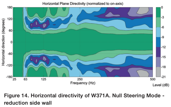
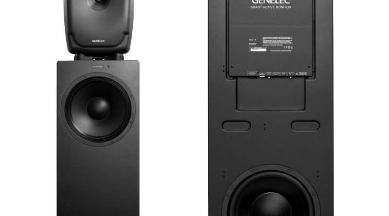
W371A - Genelec.com
W371A - Genelec.com
I'm interested on your application? Since high frequencies in general are not problem at the back, they beam from the driver or are effectively blocked by the baffle. This is of course related to the size of the transducer and the baffle. Use big or small depending what range you need to cardioid.
For good attenuation at rear you need both sound from the front and the back of the driver so it is long wavelengths only, that bend to the back from the front, around the baffle corner. If them back and front signal meet and are both equal other than opposite in phase they cancel, as with dipole. With delay on the back signal the null is steeded from side (dipole) to the back (cardioid) or anything in between.
I've got no math or acoustics background on this, just reasoning over wavelengths and some experimenting in simulator and with a mid woofer box.
All the different modes in the W371A are created by changes to delay and EQ, the null steering seems the least useful to me.
The principle is pretty straight forward, the big woofer and baffle does a lot of the directivity control to 300Hz the cancellation does the rest.
The principle is pretty straight forward, the big woofer and baffle does a lot of the directivity control to 300Hz the cancellation does the rest.
Attachments
https://assets.ctfassets.net/4zjnzn...f44ec7867f674a109a/W371A_operating_manual.pdf
There’s a few directivity plots at the end of the manual there that show a dipole-like and cardioid-like response; attenuating the rear or side response by 10dB or more.. from 50Hz upwards
There’s a mode that almost reduces floor bounce.
I think I’m going to build an experiment.
There’s a few directivity plots at the end of the manual there that show a dipole-like and cardioid-like response; attenuating the rear or side response by 10dB or more.. from 50Hz upwards
There’s a mode that almost reduces floor bounce.
I think I’m going to build an experiment.
Last edited:
Same with a true dipole woofer. 2 to 2 1/2 octaves is pretty much the useful limit. Any more that that and EQ becomes excessive and the high excursion at low frequency gives rise to IM (or Doppler) distortion.
+1 on that.
IMHO DIYers who design and build OB and dipole systems appreciate this limitation, or they resort to using a very large baffle to prevent too much loss but then you have more of an "infinite baffle" type system.
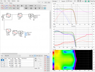
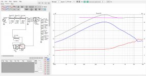
It looks like there is ~2 octaves ~400Hz - 2kHz without EQ at all? With 6db shelf and flattening the dipole peak there is 3 octaves of flat (cardioidish in this case. It is not cardioid, deepest null around 130 degrees). This is not measured but ideal 8" driver with simulated side ports and what not, tries to roughly emulate real deal. It is not too far of what you guys are saying, but isn't the dipole peak already around 2 octaves in reality as well?
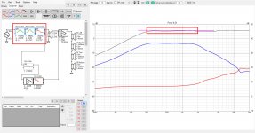
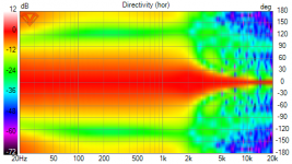
First showing just the emulated passive "cardioid" box. The second one adds filters to tame the dipole peak and add some low boost. Third image is normalized polar map.
First showing just the emulated passive "cardioid" box. The second one adds filters to tame the dipole peak and add some low boost. Third image is normalized polar map.
Attachments
Last edited:
^ The box and a large radiator will control dispersion above "dipole peak" in your sim, and keep DI flat and cardioid (or supercardioid).
In open baffle there will be "axial dipole null" where DI is practically zero, and above it DI gradually gets higher.
The lower end of usable response depends on distortion behaviour of the driver and spl wanted. In other words, on how much eq you can use.
In open baffle there will be "axial dipole null" where DI is practically zero, and above it DI gradually gets higher.
The lower end of usable response depends on distortion behaviour of the driver and spl wanted. In other words, on how much eq you can use.
^ yes the response starts to narrow as per driver size (if minimal baffle), same should happen with dipole right? What is this axial null with dipole then, it happens on frequency band that should not travel to the otherside (since it is much attenuated, 3k -20dB to 90deg inspected from the perfect monopole)? Is it the diffraction interference dip like with monopole? It looks the same for sure. See attachment, right under 3kHz there is dip in axial response due to baffle edge diffraction.
Attachment GIF cycles between ideal monopole and dipole, 8" driver on 20cm x 20cm baffle which is about the driver size. They have almost identical axial response from about 350Hz to usable frequency, around the diffraction, maybe 2kHz. That is bit more than 2 octaves without EQ. With the dipole both the peak and dip are bigger. IF the 2kHz was the top, then 3 octaves would be 250Hz, where difference in axial response is like 3dB. Difference in power response seems to be roughly 10dB though. What you guys would refer here as usable bandwidth?
Another GIF adds something cardioidish and supercardioidish to the soup.
Interesting aye, it feels like the dipole and cardioid stuff is better and the boxed one is flawed in a sense since the boxed has the back wave to be dealt with or taken advantage of but the advantage is merely bass extension. On the other hand the other two utilize the back wave to cancel sound to unwanted directions and more importantly use the front wave to cancel the back wave causing problems (due to box)!😀 DI is also flat all the usable range, in this ideal case.
All else looks the same to my eye, the stuff in "baffle step" or dipole peak and above, except the cardioid does something to the peak and diffraction dip which is probably just due to the simulation setup? I'd expect they would have pretty much peak and dip in same places as the monopole and dipole.
Is there more insight to be extracted from the GIFs? Is this too far from reality, is there something in real situation that is not here?
In which simulator cone excursion could be inspected?
All these have been generated in VituixCAD diffraction tool, except the cardioidish stuff has the filters seen in previous post trying to signal through holes on the box.
edit. latter GIF swapped, remembered the cardioidish stuff has 21x21cm baffle and the monopole and dipole 20cm 20cm. Also the gif was too fast for the eye.
Attachments

Last edited:
Edit time over since I'm again thinking and writing at the same time 😀 I was about to change the question on first paragraph about the axial null and referring it as diffraction related interference.
Well the ~3kHz dip, being a diffraction issue with the monopole, shows that yes sound goes to the baffle edge even though it looks to be attenuated by up to 20db towards 90 degree angle. Now, there is same phenomenon (edge diffraction) with dipole happening at the same time on the back of the baffle as well. I remember reading the edge diffraction makes "phantom sound source" but opposite polarity at the edge? In which case diffraction from the back signal at the baffle back edge would be in same polarity as the diffraction from the front towards the listener? This makes the peak and dip more pronounced than with monopole. Am I on the right track?
If so, or what ever the reason, the dipole shows more severe interference to listening window and this is usually kept outside the bandwidth, dubbed usable bandwidth, right? This is about the top of usable bandwidth for monopole speakers as well, and cardioid for that matter, due to beaming, rising DI. If the ideal is smooth DI.
Last edited:
I think it may be possible to evaluate the excursion by creating the loudspeaker enclosures in hornresp, then exporting the frequency and impedance data into VituixCad.^ yes the response starts to narrow as per driver size (if minimal baffle), same should happen with dipole right? What is this axial null with dipole then, it happens on frequency band that should not travel to the otherside (since it is much attenuated, 3k -20dB to 90deg inspected from the perfect monopole)? Is it the diffraction interference dip like with monopole? It looks the same for sure. See attachment, right under 3kHz there is dip in axial response due to baffle edge diffraction.
Attachment GIF cycles between ideal monopole and dipole, 8" driver on 20cm x 20cm baffle which is about the driver size. They have almost identical axial response from about 350Hz to usable frequency, around the diffraction, maybe 2kHz. That is bit more than 2 octaves without EQ. With the dipole both the peak and dip are bigger. IF the 2kHz was the top, then 3 octaves would be 250Hz, where difference in axial response is like 3dB. Difference in power response seems to be roughly 10dB though. What you guys would refer here as usable bandwidth?
Another GIF adds something cardioidish and supercardioidish to the soup.
Interesting aye, it feels like the dipole and cardioid stuff is better and the boxed one is flawed in a sense since the boxed has the back wave to be dealt with or taken advantage of but the advantage is merely bass extension. On the other hand the other two utilize the back wave to cancel sound to unwanted directions and more importantly use the front wave to cancel the back wave causing problems (due to box)!😀 DI is also flat all the usable range, in this ideal case.
All else looks the same to my eye, the stuff in "baffle step" or dipole peak and above, except the cardioid does something to the peak and diffraction dip which is probably just due to the simulation setup? I'd expect they would have pretty much peak and dip in same places as the monopole and dipole.
Is there more insight to be extracted from the GIFs? Is this too far from reality, is there something in real situation that is not here?
In which simulator cone excursion could be inspected?
All these have been generated in VituixCAD diffraction tool, except the cardioidish stuff has the filters seen in previous post trying to signal through holes on the box.
edit. latter GIF swapped, remembered the cardioidish stuff has 21x21cm baffle and the monopole and dipole 20cm 20cm. Also the gif was too fast for the eye.
By going this route, you're basically using Hornresp to figure out the enclosure, and VituixCad to figure out the crossover
Hi Patrick Bateman, that might yield some interesting experiments 🙂 Does hornresp export more than single axis response? Its been a while since I used it
First off, I figured out that there's no need to trace the SPL and impedance graphs in Hornresp - you can just export them as FRD and ZMA files, respectively. Way easier.
As far as directivity stuff, as far as I can see, we're kinda stuck:
1) vituixcad can simulate baffle shapes and calculate their directivity, both open baffle and closed. But I'm not aware of any way to simulate a three dimensional box in vituixcad. (There may be and I just don't know it.)
2) the combination of ATH and ABEC can simulate boxes in three dimensions
3) Hornresp can simulate a bevy of box types, but it's ability to simulate directivity is limited to certain box types.
4) Only Vituixcad can simulate sophisticated crossovers.
So you have to combine parts of each to get what you want. Being able to export FRD and ZMA files is a Godsend.
Also, I think this state of affairs is probably ideal. A big part of the reason that Abec is my least favorite tool to use, is BECAUSE it can do so much. I can knock out a sim in hornresp or Vituixcad in a matter of minutes, but everytime I try to do sims in Abec or even Akabak, it becomes a day-long-affair, because they're so complex.
Yeah only front panel effects are simulated, it is some simple ray tracing math for everything to be real time.1) vituixcad can simulate baffle shapes and calculate their directivity, both open baffle and closed. But I'm not aware of any way to simulate a three dimensional box in vituixcad. (There may be and I just don't know it.)
My favourite part as well, real time behaviour, change a parameter and effect is simultaneous.I can knock out a sim in hornresp or Vituixcad in a matter of minutes
Effects of back of the box are missing in VCAD sims but their magnitude seem to be secondary to what the front does especially to listening window. Point is if front of the box/construct does not reach the response one is looking for the back of the box can't fix it. One should revisit the front until response is what you are looking for. I like to think we have lost control when sound propagates past first significant edge, our construct diminishes in size compared to propagating wave 343m/s and so does the effectiveness of manipulation with the construct. Even if something on the back would have perfect control on sound that gets there it couldn't cancel what happened at front edge just because of extra path length.
Well, there is effect to great off axis angles, about past 90degrees where sound around the box interacts and lays an interference pattern. To simulate this kind of effects BEM sim is needed. Or prototype and measure 🙂
@john k...
My college professors used to remind us that books are out of date by the time they are published... in my field it is certainly true. Of course for those learning fundamentals of anything, eg. cell biology, it is useful
https://www.audiosciencereview.com/...s-rainmaker-speaker-review.40906/post-2219330
AFAIK, you were doing this 20 years, placing woofers at opposite ends of the room, out of phase with the other, which mimicked a dipole subwoofer, IIRC.
You were certainly ahead of the curve...
Now... (looking around).. where are my Note plans... I might just have to give it a spin (orama) ...
Last edited:
- Home
- Loudspeakers
- Multi-Way
- Cardioid and Sealed cabinet ala John Kreskovsky