@Ben measurements are from 1m on axis.
Thanks.
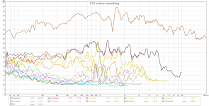
Smoothing?
Distortion?
B.
Still have some things to take care of before I remeasure, experiment with enclosures and reversing the driver side. If those don't lead to satisfactory results with the top end though, has anyone experimented with integrating these with a ribbon, AMT or horn?
I wonder in particular, for the sake of a cheap fix whether something like this could integrate well above 6-8KHz: https://www.parts-express.com/eminence-apt-150-super-tweeter-with-horn-100-x-50--290-534 - or Eminence ASD1001 1" HF Titanium Horn Driver 1-3/8"-18 TPI mated with the same horn. Seems to me that early reflections might still have a different color than from the DML, but I'm not sure. I'm also having a hard time finding any kind of subjective opinions on relative quality of horn drivers like these.
I wonder in particular, for the sake of a cheap fix whether something like this could integrate well above 6-8KHz: https://www.parts-express.com/eminence-apt-150-super-tweeter-with-horn-100-x-50--290-534 - or Eminence ASD1001 1" HF Titanium Horn Driver 1-3/8"-18 TPI mated with the same horn. Seems to me that early reflections might still have a different color than from the DML, but I'm not sure. I'm also having a hard time finding any kind of subjective opinions on relative quality of horn drivers like these.
Some more on edge damping: https://riunet.upv.es/bitstream/handle/10251/3347/tesisUPV2873.pdf - see chapter 4
The major changes have been observed at low and mid frequencies, where the edge radiation was predominant. In general terms, free and clamped conditions boost bass power, at the expense of smoothness compared to elastic boundaries. Wavenumber domain analysis has shown that strong pressure variations would be perceived, both in the frequency response, and and spatially on moving inside the listening area for these two conditions, this makes them inadvisable in multichannel audio reproduction.
Alternatively, elastic boundaries are a compromise between clamped and free, that can be realized with different elastic materials. For mid frequencies, on-axis responses were smoother for elastic boundaries than clamped and free edges, regardless of the elastic material employed. Moderate variations were found in directivity patterns on using clamped and free but not on elastic boundary types 1 and 2, where half or the entire part of the support is filled with material. As a consequence, both boundary conditions can be used alternatively with similar results for elastic materials with proper flexibility. Elastic boundary type 3 is a modified version of simply supported, but including elastic material between panel and housing. According to the results, it has no primary advantages over the two other elastic boundaries. Therefore, its use is not recommended, considering the problems that will arise on manufacture in a real MAP frame, as mentioned in Section 1.2
Finally, the appearance of new undesired replicas of the plane wave field that were drawn in Section 3.5, is minimized for elastic boundaries with flexible materials. As a consequence, with the proper selection of materials for elastic boundaries, the effect of edge boundary conditions on the reproduced replicas can be decreased to a minimum.
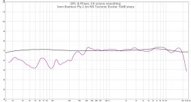
For interest here is a 3mm bamboo ply panel measured at 2.5 metres and driven by a Tectonic Elements exciter.
I posted detailed results of a whole series of measurements on materials and different exciters over at Parts Express Techtalk about a year ago. Link below:
Tech-Talk postings
Note that there was significant variation with both exciter and panel material choices.
I posted detailed results of a whole series of measurements on materials and different exciters over at Parts Express Techtalk about a year ago. Link below:
Tech-Talk postings
Note that there was significant variation with both exciter and panel material choices.
Panel Size was 380 x 530mm.
I had the panels cut by ponoko.com in both 3mm Bamboo Ply and in double layer corrugated cardboard.
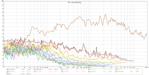
Nice , 380x530 still a reasonable size. although it servers more as a mid high freq range driver. its amazing it extends to 20khz never seen exciters do.
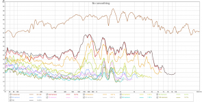
but the mearuements are slightly smoothed 1/6 is pretty heavy and 10 db increments is rather heavy to, both makes the plot allot smoother then it is
is there any effciency? i know its hard to measure when it is not calibrated 🙁 just like my setup i recon your rew is not calibrated either ? since 70 would be somewhat low. would be 76 at 1 meter
Distortion. Also including IR even though it seems like gobbledygook. Group delay might be right, I'm not sure. Doesn't look great, but perhaps we wouldn't expect it to given the physics of the speaker.
Attachments

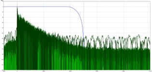
Most of that seems to be in the extreme low end. Crossing at 70Hz looks like it'd be reasonable. If I set the window to look at that frequency upwards, it says THD is 9.10%. At the moment I'm actually crossing at 120, which it calculates as 4.05% THD.
Maybe I'll play with EQing this flat in the next few days and seeing what happens to the distortion graph. Other reviews of DMLs seem to report that a measured flat EQ in the treble sounds subjectively too bright, so maybe this is not too bad of a place to start from. Framing and damping seems intuitively like it would help, but some of the papers posted earlier suggest that those would be more effective at taming the bass, unfortunately.
I'm also curious to try IR-based speaker and room correction, although it seems like all bets might be off with that approach.
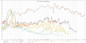
With the exciter facing outwards, response is flatter and distortion is worse.
I could hear some buzzing somewhere in the middle of the sweep, which I imagine might correlate to the peak in distortion. Maybe if I'm lucky that has to do with the panel resting on a ragged edge of honeycomb (very ugly sound if you scrape something along it). If that's the case, it ought to get better with better mounting. Otherwise, maybe it's down to the honeycomb being too thick, the exciter itself or the technology... or other ideas?
I could hear some buzzing somewhere in the middle of the sweep, which I imagine might correlate to the peak in distortion. Maybe if I'm lucky that has to do with the panel resting on a ragged edge of honeycomb (very ugly sound if you scrape something along it). If that's the case, it ought to get better with better mounting. Otherwise, maybe it's down to the honeycomb being too thick, the exciter itself or the technology... or other ideas?
Attachments
Distortion is indeed really high , the peak is the resonance of the whole panel usually , but distortion should be far less then 5% and for sure lower the 70 🙂 haha another thing it looks like the efficiency is really really low and you might be overly driver bing the exciter itself ?
Over driving is possible. I've got an extra pair of exciters and panels not yet wired up. I can try running them in series to see if the increased sensitivity (matched roughly for overall level) helps.
As for efficiency, the absolute measurement of dB could be way off. I misunderstood what the REW SPL calibration feature was about and set it to something arbitrary.
I'm not sure if the EMM-6 mic calibration comes with absolute SPL values included. If it does I'll be sure and use those on the next measurement.
I'm not sure if the EMM-6 mic calibration comes with absolute SPL values included. If it does I'll be sure and use those on the next measurement.
Yes, truly awful-looking distortion measurements and riddled with nasty resonances. Proves once again, speakers you make yourself always sound great to you but sometimes only you.Distortion is indeed really high...
But what can be done? The foam-core poster-board multiple-exciter speakers in another thread measure a tiny bit better (3-5% THD). Maybe the paper facings help damp their racket a bit - and we also see results for damping globs stuck on.
http://www.diyaudio.com/forums/full-range/272576-study-dmls-full-range-speaker.html
So I'd stick on something to damp starting with rows of duct tape or self-stick mylar film, covering as much surface possible without excess weight.
To me, the DML approach using an exciter from Parts Express seems unpromising even if the analogous Magnepan is respected in some circles. Shaking a board to cleanly reproduce sound? Using crude $15 vibrator mechanism and hoping it will be acceptably linear in its motion? Although far from perfect, the cone, magnet, and suspension of cone drivers have been refined for nearly a century.
Great to see experimentation. Very brave to measure results and even braver to post them... even when goading was necessary. Thanks for following through.
But very necessary to measure performance because as we all know, speakers you make yourself....
Ben
Last edited:
Yes, truly awful-looking distortion measurements and riddled with nasty resonances. Proves once again, speakers you make yourself always sound great to you but sometimes only you.
But what can be done? The foam-core poster-board multiple-exciter speakers in another thread measure a tiny bit better (3-5% THD). Maybe the paper facings help damp their racket a bit - and we also see results for damping globs stuck on.
http://www.diyaudio.com/forums/full-range/272576-study-dmls-full-range-speaker.html
So I'd stick on something to damp starting with rows of duct tape or self-stick mylar film, covering as much surface possible without excess weight.
To me, the DML approach using an exciter from Parts Express seems unpromising even if the analogous Magnepan is respected in some circles. Shaking a board to cleanly reproduce sound? Using crude $15 vibrator mechanism and hoping it will be acceptably linear in its motion? Although far from perfect, the cone, magnet, and suspension of cone drivers have been refined for nearly a century.
Great to see experimentation. Very brave to measure results and even braver to post them... even when goading was necessary. Thanks for following through.
But very necessary to measure performance because as we all know, speakers you make yourself....
Ben
hmm i get with the paper foam board and diy motor, definitely under 4%, i will make a new one tonight and post some measurements. i form the foamcore into an aerofoil or half a cylinder to increase stifness. spl matches my 12 inch woofer in OB so not to shabby. only anoying thing is the foamboard has to dry a pretty long time, so i hope ill manage.
Last edited:
Ben, don't thank me for following through. I responded to the request for distortion not because I was goaded but because it was reasonable and because it was another chance to allow you to participate in the thread without being rude and condescending. It failed.
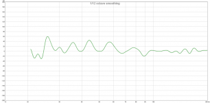
WrineX, to confirm the over driving hypothesis, I tried playing Chet Baker - "Round Midnight" with REW's SPL meter open and found that I was running the frequency sweep probably about twice as loud as I ought to have been. Fixing that, the resulting graph has as similar overall shape...
... how do I get REW to report THD over the whole range though? I noticed that if I accidentally clicked on the far left of the graph, clearly below where the panel is operating in any kind of reasonable regime, it'll report THD at exactly that frequency - for example, around 500% at 20Hz. Heh.
For the record, picking a couple other points along the spectrum, at 223Hz it's 5%, the peak at 557Hz is 0.477%, trough at 756Hz is 2.15% (with a local peak in distortion), and generally it looks like below 1% from there on up.
Attachments
- Home
- Loudspeakers
- Planars & Exotics
- Carbon fiber + nomex honeycomb sandwich DML panel construction project