
I built an entire preamp using mostly c0g and it sounds great. I wouldn’t use x5r or x7r in the audio path, but c0g/np0 is fine.Thank you for these measurements. It seems I need to revise my pre-conceptions about ceramic caps after modern improvements in technology - I would never have considered using them in a feedback loop but that last plot is impressive.
I'm currently browsing Digikey to order some and I will be able to compare them to the polystyrenes that I used on previous builds with the same design and pcb.
I have designs in a couple of commercial phono stages that use nothing but SMD devices, and all of the critical caps are C0G. They have achieved "critical success"- i.e. reviewers like them. The DIY versions are also very well received. The use of C0G caps should not be feared...
Yes the availability of those caps in SMD packaging is a bonus advantage on crowded boards as I'm limited by the 10 x 10 cm size of most economical "prototype" PCB fabs like JLCPCB. My phono stage design barely fits a single channel on that board size using through-hole and 4 copper layers.phono stages that use nothing but SMD devices
I would only use class I for signal.On top of that, you have the microphony of class 2 capacitors
I’ve pretty much switched my whole pcb methodology when it comes to audio signals. I almost always exclusively use c0g/np0 unless I need 1uf or greater. Which thanks to the work of Tom and others here, I switch to the Nichicon Muse BP caps which they measured as essentially transparent in the THD department.
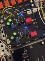
Here was the last vinyl RIAA/pre-amp I made for my amp. I tossed a wima on there just to spice up the visuals a bit, but the previous version just used c0g in its place and it sounded great. I never measured it, but it was based on the Elliot sound RIAA preamp, and it sounded way better than the commercial pre-amp it replaced.
Here was the last vinyl RIAA/pre-amp I made for my amp. I tossed a wima on there just to spice up the visuals a bit, but the previous version just used c0g in its place and it sounded great. I never measured it, but it was based on the Elliot sound RIAA preamp, and it sounded way better than the commercial pre-amp it replaced.
Attachments
When you size a coupling capacitor for a 2 Hz corner frequency, you still have some 10 % of the signal voltage across the capacitor at 20 Hz
Thanks for pointing this out, I wasn't even aware that ceramics displayed a large voltage capacitance coefficient. I'll be reading about this in the next few days.
While we're on the subject of ceramics....
Below is the tape loop amplifier of my vintage amp, which I upgraded with hi-fi opamp. I also designed a clone board with the schematic attached; PCBs are in the mail. On the picture the 22p compensation caps seem ceramic, but who knows which class - Information is scarce on this oldie.


I have them in my crosshairs for further upgrade but then reason kicks in and deem that useless, as part of a high pass filter with a corner frequency over 320 KHz the cap is basically out of the audible signal path. Is this a correct reasoning?
With the tape loop amp clone I could experiment with various cap types to see if there is audible difference, and as a baseline standard I'll put garden variety type I ceramics.
In this case I don't think the capacitance/voltage coefficient is an issue as the DC bias is negligible (consumer level signal), otherwise they wouldn't have designed it that way, right?
Below is the tape loop amplifier of my vintage amp, which I upgraded with hi-fi opamp. I also designed a clone board with the schematic attached; PCBs are in the mail. On the picture the 22p compensation caps seem ceramic, but who knows which class - Information is scarce on this oldie.
I have them in my crosshairs for further upgrade but then reason kicks in and deem that useless, as part of a high pass filter with a corner frequency over 320 KHz the cap is basically out of the audible signal path. Is this a correct reasoning?
With the tape loop amp clone I could experiment with various cap types to see if there is audible difference, and as a baseline standard I'll put garden variety type I ceramics.
In this case I don't think the capacitance/voltage coefficient is an issue as the DC bias is negligible (consumer level signal), otherwise they wouldn't have designed it that way, right?
Last edited:
They are NP0, also known as C0G, so they are class 1. The black stripe indicates NP0. Ceramic capacitors of 220 pF or less are almost always class 1 anyway.
Thanks a lot Marcel, that's good to know. Replacing them would really have been a mistake.The black stripe indicates NP0. Ceramic capacitors of 220 pF or less are almost always class 1 anyway
Last edited:
It's a common thing to use ceramic disks, identified as C0G or otherwise, in such a position. For example, the high gain phono stage with the c. -130dBc distortion level at 1kHz uses such circuitry in several locations, with typical roll offs in the 300kHz region.
Clearly at 1kHz the frequency ratio relative to 300khz is 300:1 or so, but what happens at 10kHz, for example, when the ratio is an order of magnitude lower?
Well, the answer, in this particular case, is that the distortion is c. 17dB worse at the same reference level of 6dBv and is almost entirely 2nd order. This is entirely consistent with the reduction in the feedback factor in the amplifier stages due to the increase in frequency and the increase in amplitude in the 46dB buffer due to the RIAA characteristic and there is no evidence that any secondary sources of distortion, say from the bandwidth limiting caps, comes into play.
Your schematic postFor example
This is a very interesting design, where can I find more information about it? Thanks
Ultra high spec. opamp MC/MM phono, warp "elliptic" filter, line, headphone amps.
This is a project that has been on Audio Karma for about a year and has had a number of revisions, additions and upgrades.
There are about 150 of the units in various versions out in the field and it was repeatedly suggested by builders that a thread be opened in DIYaudio- so despite some reluctance here it is.
As the title suggests, it is opamp based, and is hardly unique, but it has some unusual features and has stellar specs and is pretty easy to build.
Some features:
1. Optional parallel input...
- wynpalmer2
- Replies: 337
- Forum: Analogue Source
There is also an extensive Audiokarma thread on the associated designs.
Thanks a lot! This project seems headed in the direction I wanted to explore in my experimentation: fet inputs and op-amps applied to phono stages, to compare with my current discrete 39-transistor/channel design which is time extensive to build.There is also an extensive Audiokarma thread on the associated designs
Last edited:
- Home
- Design & Build
- Electronic Design
- Capacitor type and quality recommendations for RIAA preamp cartridge loading