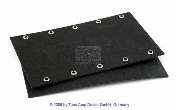
I am planning on using two of these caps in my power supply.
I will be wiring things up PTP.
EZP-V60107MTC Panasonic | Mouser
https://www.mouser.com/datasheet/2/315/RDL0000C251-1772694.pdf
What would be an acceptable way of connecting the wires to the pins?
I thought about using a PCB board but I haven't found any that have holes large enough for the 1.2mm diameter pins nor any that have the proper hole spacing of 52.5mm by 20.3mm.
I can solder directly to the pins but that seems inelegant.
TIA
Dave
I did order some from a supplier overseas without too much difficulty but I had the Gerber files. I wouldn't know where to start designing my own. What is Osh Park?
Small pcbs can be reasonable, Osh Park will make three pcbs for $5 per sq in.
Of course you can just drill some perf board, that would be very cheap.
But you'd also want some mechanical strength for those large caps.
The boards will probably have to be horizontal.
If you make pcbs, maybe other parts of the circuit can be combined with the
large caps on the same board.
Of course you can just drill some perf board, that would be very cheap.
But you'd also want some mechanical strength for those large caps.
The boards will probably have to be horizontal.
If you make pcbs, maybe other parts of the circuit can be combined with the
large caps on the same board.
Last edited:
You can make an eyeletted board easily and any size you want.
Check Hoffman , Tube Amp Doctor, etc.
Check Hoffman , Tube Amp Doctor, etc.
I thought about an eyelet type board but the pins only protrude 4 mm at best so there won't be much if anything left exposed to solder to.
Then just put a little hook bend in the end of your wire, loop it around the cap pin and solder it there. You can then mount the caps to the chassis with straps or clamps
Not too bad.I thought about an eyelet type board but the pins only protrude 4 mm at best so there won't be much if anything left exposed to solder to.
4mm will just clear through eyelet and in any case molten solder will pool inside the hole which has metal walls, it´s not as if you had a 3 mm deep hole inside a thick fiberglass board or something with only the very tip reaching copper at the other end.
I am quite certain that if you solder those 4 mm legs inside those eyelets you will not be able to remove them afterwards even if using a hydraulic press.
You will tear those legs out of the capacitor first.
I make my own PCBs but for simple one-off work like yours still use my trusty bench eyelet press I bought in 1969 😱 "to make boards like Leo does"
Still using it to this day, faithfully riveting terminals in my speakers, plus, as said above,the odd eyeletted board.
Given the flawless 52 year service , most useful helper and best investment I can think of 🙂
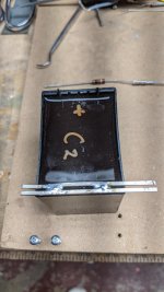
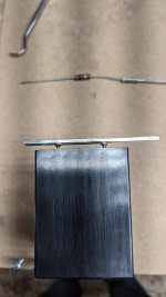
I think I'm going to try something like this. In the final build I can hook the B- side of the caps together with longer pieces of bus wire. It also gives me a nice place for bleeder resistors and the choke hookups.
Thanks for all the help. I'll work on learning a PCB design program as that seems valuable.
Thanks for all the help. I'll work on learning a PCB design program as that seems valuable.
Attachments
I have soldered mine to a cheap FR4 protoboard (like eg https://www.ebay.de/itm/13383145926...SojrH60eX7t2IZbjpDHC|ampid:PL_CLK|clp:2047675), some extension wire and holes in the board for fixing it to the chassis.
You could take a chunk of PCB stock and saw or grind (or mill or rout) away copper, depending on what tools are available. Or score the strip you want to remove with a knife, then heat it with a soldering iron and peel it off. Or lay down patches of plastic tape and etch away the copper you don't want.
- Home
- Design & Build
- Construction Tips
- Capacitor to Wire Connection?