question
How do you determine the capacitor outside foil
Directions
In this situation circuit
C 307
470NF
I know two rules in this situation
1) The outside foil facing
The lower resistance in the circuit
2) the outside foil facing ground in the circuit
In this situation are there different rule ? C 307 -470NF
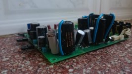
Attachments
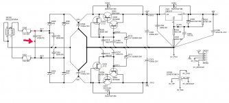
In this situation are there different rule ? C 307 -470NF
That's an AC circuit, so either way is ok. You do have ground loops as shown.
The positive and negative supply grounds should be separated.
Last edited:
That's an AC circuit, so either way is ok. You do have a ground loop involving the input common.
THANKS rayma 🙂
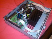
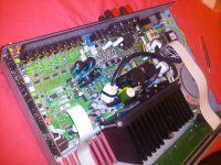
I went back to work on my old arcam amp projectYour 15v3 rails will have 14.3 on them as you have the BE junction to consider.
http://www.diyaudio.com/forums/solid-state/248632-my-diy-arcam-fmj-32-amp-mod.html
Attachments
-
 a32 p.JPG134.7 KB · Views: 141
 -
 12963869_3177430037931_4701347716070471417_n.jpg76.8 KB · Views: 55
 -
 12963439_3177430317938_8145563124174848038_n.jpg93.1 KB · Views: 121
 -
 12963439_3177430317938_8145563124174848038_n (1).jpg93.1 KB · Views: 110
 -
 12718189_3177430797950_986586462370047917_n.jpg58.2 KB · Views: 115
 -
 1899843_2437378177097_354436823_o.jpg245.2 KB · Views: 50
 -
 1617612_2437378137096_60687127_o.jpg299.9 KB · Views: 54
Last edited:
In some countries, one of the AC mains terminals (AC1, AC2) is wired to 'Neutral', and the other to 'Active'. The Neutral is bonded to protective earth somewhere nearby, and so the Neutral effectively has very little AC voltage on it relative to amp chassis. If that is the case then 'Neutral' side of C307 would preferably be the 'outside' foil.
In some countries, one of the AC mains terminals (AC1, AC2) is wired to 'Neutral', and the other to 'Active'. The Neutral is bonded to protective earth somewhere nearby, and so the Neutral effectively has very little AC voltage on it relative to amp chassis. If that is the case then 'Neutral' side of C307 would preferably be the 'outside' foil.
thanks trobbins
Another question
I Thinking to increase capacitor value
C300
C301
How much
I can increase the value?
I Thinking to increase capacitor value
C300
C301
How much
I can increase the value?
Arrgh - the AC1 and AC2 are coming from the secondary windings of a transformer - sorry for the misleading post earlier.
C307 would normally be two separate snubber networks - see Quasimodo threads on this forum.
C307 would normally be two separate snubber networks - see Quasimodo threads on this forum.
Rule 2 is merely a particular case of Rule 1.dazzz said:I know two rules in this situation
1) The outside foil facing
The lower resistance in the circuit
2) the outside foil facing ground in the circuit
This rule applies to capacitors in sensitive positions in signal circuits. Your C307 is merely in an uncritical position in a PSU so no need to worry about such matters.
thank broRule 2 is merely a particular case of Rule 1.
This rule applies to capacitors in sensitive positions in signal circuits. Your C307 is merely in an uncritical position in a PSU so no need to worry about such matters.
I Thinking to increase capacitor value
C300
C310
How much
I can increase the caps value safely ?
Last edited:
You can increase them a bit, but no advantage in a big increase and some possible disadvantage. Why do you want to change them? Did the original designer get it wrong?
You can increase them a bit, but no advantage in a big increase and some possible disadvantage. Why do you want to change them? Did the original designer get it wrong?
When it comes to linear voltage regulators
I understand the issue well enough.
Preamp had a problem in the past of the display screen to dim mode. There was a noise frequency of approximately 1K from the speakers
I solved the problem almost completely by adding a resistor value of 0.47 ohm 2 watt
in the output of the lm317 -That's how I solved the problem of the ESR of a output capacitor
the 5 volt supply is for the digital volume and the amp display .
(the 15 volt is for the op amps supply)
I understand less
Voltage Regulators are based on transistors
So I ask this because the filtering capacitors
C300
C310
Normal mode power supply based only on voltage regulators like LM317
I certainly would increase the capacitors to improve the ripple rejection.
But because of the power supply of the preamp is also based on Shunt Regulators with the fact that I now without a lot of experience on shunt reg so I do not know what the effect of raise the caps value on the circuit.
I hope I was able to explain it clearly 🙂
Attachments
Increasing the reservoir capacitors will reduce the ripple going in to the regulator, and therefore possibly reduce the ripple coming out. I say 'possibly' because in some PSUs the ripple is limited by grounding arrangements rather than cap values. You can calculate or measure the ripple, and see what improvement you need.
I am unclear what this has to do with instability of a linear regulator caused by the inductive output impedance reacting with a capacitive load.
I am unclear also what this has to do wth a shunt reg as I can't see a shunt reg in that circuit.
I am unclear what this has to do with instability of a linear regulator caused by the inductive output impedance reacting with a capacitive load.
I am unclear also what this has to do wth a shunt reg as I can't see a shunt reg in that circuit.
I am unclear also what this has to do wth a shunt reg as I can't see a shunt reg in that circuit.
Attachments
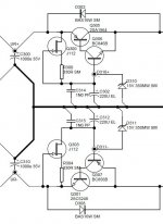
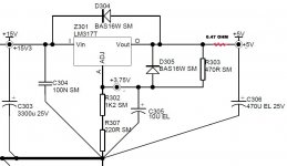
I still can't see a shunt reg. I see a JFET wired as a CCS feeding a zener, acting as voltage reference for a complementary pair follower. OK, you could say that the zener is a shunt reg itself - but that is not normally what audio people mean when they talk of a shunt reg. They mean an active circuit, not a single component.
I still can't see a shunt reg. I see a JFET wired as a CCS feeding a zener, acting as voltage reference for a complementary pair follower. OK, you could say that the zener is a shunt reg itself - but that is not normally what audio people mean when they talk of a shunt reg. They mean an active circuit, not a single component.
DF96
My intention was again that I have no experience with this part of the circuit and the effect of the filtering capacitors on it
So that's why I asked about raising the value of the capacitors and the effect on the circuit.
If the circuit dont have Constant Current based on a transistors that drive the the zener diode
I would not ask
Again never built voltage regulator circuit based on transistors
So dont catch me on the the word "shunt" i thought it Shunt Regulators
Because transistors and zener diode
In post 14 I said
If that does not answer your question then you are not asking the question you think you are asking.DF96 said:Increasing the reservoir capacitors will reduce the ripple going in to the regulator, and therefore possibly reduce the ripple coming out. I say 'possibly' because in some PSUs the ripple is limited by grounding arrangements rather than cap values. You can calculate or measure the ripple, and see what improvement you need.
In post 14 I said
If that does not answer your question then you are not asking the question you think you are asking.
I understood bro
Thanks for the help
This PSU will have a poor lloadregulation.
The C307 is totally incritical as for placing it on the board.
Although I preffer to make all wiring on the AC-lines as symmetrical to the powerlines and zero/ground terminals/supplylines.
The C307 is totally incritical as for placing it on the board.
Although I preffer to make all wiring on the AC-lines as symmetrical to the powerlines and zero/ground terminals/supplylines.
- Status
- Not open for further replies.
- Home
- Amplifiers
- Power Supplies
- capacitor outside foil Directions in this situation circuit