I need a help selecting values for Rb(1-8) and Cin(1-8) and Cout(1-8) on my circuit. I'm pretty new to designing analogue circuits.
Unfortunately the forum wont let me post a picture (I need to have made more posts?), so I'll have to describe it.
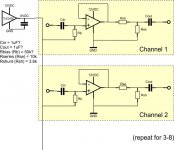
The circuit is going to take audio from a mixing desk. I will be tapping into the "pre-fade output" which is just after the pre-amp for the mics. The level is too high for me recorder, so I need to attenuate it. I don't have specs for the output, but the manual says it's at "professional line level". As such, I intend to make a "copy" of the signal, using a TL071 Op Amp, and then attenuate the output.
There will be 8 mono audio channels - so 8 taps from the desk and 8 copies of the main part of the circuit.
I have plenty of TL071 Op Amps that I intend to run from a 12VDC source. I intend to use 1 per channel.
I intend to use a TLE2426CLP chip to provide a 6VDC bias for each signal into each TL071.
As far as I know, I only need one TLE2426CLP, but I need a resistor between the output and each + input on the TL071. I'm calling these Rb(1-8)... but I don't know what value I need for each. I'm assuming they'd all be the same.
Since I'm using a DC bias, I need a DC blocking cap between signal in and TL071 (I'm calling these Cin(1-8) ), and also on the output of the TL071 before output to the recorder (I'm calling these Cout(1-8) ).
I thought I had it figured out, as I was going to use a 1uF on Cin, and a 50k for Rb. According to the RC Calc I'm using, it says a cutoff just under 8Hz. However, when I looked to get the caps, apparently I need to use C0G and they don't seem to offer values that high, and I shouldn't use X7R for audio because they are noisy. That's where I'm stuck!
If I raise the Rb value enough so I can use a C0G (biggest value I can find is 10nF), this means using a 500k Rb. Is that going to be ok or is the impedance too high?
How will I overcome the problem with the output impedance? As far as I know, the recorder input impedance is 20k, which if I use the 10nF cap is going to be cutting off around 800Hz, which is totally unacceptable.
Unfortunately the forum wont let me post a picture (I need to have made more posts?), so I'll have to describe it.
The circuit is going to take audio from a mixing desk. I will be tapping into the "pre-fade output" which is just after the pre-amp for the mics. The level is too high for me recorder, so I need to attenuate it. I don't have specs for the output, but the manual says it's at "professional line level". As such, I intend to make a "copy" of the signal, using a TL071 Op Amp, and then attenuate the output.
There will be 8 mono audio channels - so 8 taps from the desk and 8 copies of the main part of the circuit.
I have plenty of TL071 Op Amps that I intend to run from a 12VDC source. I intend to use 1 per channel.
I intend to use a TLE2426CLP chip to provide a 6VDC bias for each signal into each TL071.
As far as I know, I only need one TLE2426CLP, but I need a resistor between the output and each + input on the TL071. I'm calling these Rb(1-8)... but I don't know what value I need for each. I'm assuming they'd all be the same.
Since I'm using a DC bias, I need a DC blocking cap between signal in and TL071 (I'm calling these Cin(1-8) ), and also on the output of the TL071 before output to the recorder (I'm calling these Cout(1-8) ).
I thought I had it figured out, as I was going to use a 1uF on Cin, and a 50k for Rb. According to the RC Calc I'm using, it says a cutoff just under 8Hz. However, when I looked to get the caps, apparently I need to use C0G and they don't seem to offer values that high, and I shouldn't use X7R for audio because they are noisy. That's where I'm stuck!
If I raise the Rb value enough so I can use a C0G (biggest value I can find is 10nF), this means using a 500k Rb. Is that going to be ok or is the impedance too high?
How will I overcome the problem with the output impedance? As far as I know, the recorder input impedance is 20k, which if I use the 10nF cap is going to be cutting off around 800Hz, which is totally unacceptable.
Not to dampen your enthusiasm for building a circuit, but I think you could do this simply with a 'Y' cable type of arrangement.
You say your preamp output is too high for the recorder, but you could turn the mike preamp gain down to get a proper level, and then adjust the channel fader to get whatever else you need done?
It'd help to know what kind of mixing board you have and what kind of recorder you have. The details are important, even if you do actually need active circuitry to get this to happen. However, I bet that you really could avoid everything but cable and connectors and get a reasonable system worked out. No circuitry means no power supply, no enclosure, and no circuitry to contaminate your signal.
It needs to be active. The desk is a Peavey but I'm not sure of the model - it's one of the live series that has 8 mix channels and on board FX.
The desk has an insert on a single TRS jack. Using that jack I need to feed the send back to the return untouched. Using a Y cable already drops the signal going back to the desk, and reducing the mic pre then reduces it further to the point where it is now interfering with the ability to mix front of house, as the faders are now brickwalled to the top. Sound quality is also affected, probably mainly due to drop in signal to the main mixing section..
The recorder is an 8-channel STAudio ADC/DAC2000.
No, the recorder has 8 channels, which are unbalanced consumer level line inputs (mono 6.35mm jacks), and are recorded individually. Mixing down the recording will be done on the PC using software at a later point.
The idea of making 8 taps is so I can take 8 separate channels into the recorder.
The idea of making 8 taps is so I can take 8 separate channels into the recorder.
Hi, well that extra info makes All the difference !
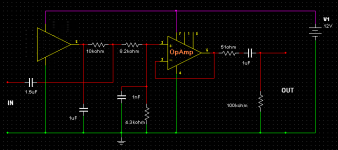
Try this circuit for each input.
With the 1.5uf Cap = -3db @ 20hz & With the 1nf Cap = -3db @ 56kHz
Pro Level = 775mV in & Consumer Level = 243mV Out
As i think you realise, you only need one TLE2426 for All 8.
Instead of FET TL071's etc, i would consider non Fet's with this circuit. And why not use 2 x Quad OpAmps")
Try this circuit for each input.
With the 1.5uf Cap = -3db @ 20hz & With the 1nf Cap = -3db @ 56kHz
Pro Level = 775mV in & Consumer Level = 243mV Out
As i think you realise, you only need one TLE2426 for All 8.
Instead of FET TL071's etc, i would consider non Fet's with this circuit. And why not use 2 x Quad OpAmps
Attachments
First of all, thank you, your help is really appreciated.
Secondly... Sorry, as a beginner I expect I'm totally misunderstanding the circuit... could you perhaps explain why you've made those changes?
Isn't the point of feeding the input direct to the OpAmp that you present a high impedance, and leave the signal you're tapping intact? It looks like you've put the attenuation before the OpAmp - wont that mean a lower impedance on the tap, and the desk signal being affected?
I'm not sure what the purpose of the 56kHz roll off is? This is audio, mostly fed from mics - wont there be virtually nothing significant above 20kHz anyway?
I guess the 100k resistor on output is to present 100k output impedance, but what's the 51 on the output for?
Also, this doesn't really address the problem of what type of capacitors I should be using?
As for why I'm using the TL071 chips... I have them already...
TL071CN 20 chips
MCP6024 5 chips
LM358NG 25 chips
NE5532P 10 chips
The LM358 is apparently "bad"... lots of crossover etc. and really intended for battery powered circuits. I intend to use these as my experimental chips - they were insanely cheap which is the only reason I bought them.
MCP6024 intended for 5V stuff as far as I can tell. I was thinking these would be good for use with microprocessors when I want to feed them a signal from an electret or line signal.
NE5532P are apparently complete overkill for this, and would be better for when I try to build a pre-amp system for my acoustic resonator and guitars. I wont even be trying that until I know more though. I snapped them up again because opportunity was there to grab them dirt cheap, and apparently they're common in a lot of audio equipment.
Your mixer outputs should be fairly lowish impedance. Check the manual. So feeding into my circuit will be just fine.
Yes i've put the attenuation before the OpAmps, as that's the better way to do it. The way you had it, doesn't present a low output impedance to the recorder, as mine does. The 100k resistors are only to bias the output cap's to ground. The actual output impedance/resistance in this case, are the 51 Ohm resistors in series with the outputs. These help prevent the output screened cables capacitance from causing the OpAmps to oscillate.
The purpose of the 56kHz roll off is to filter any RF etc. You can change the cap values to 1.5nf = around 24kHz if you wish.
Use whatever type of capacitors you like. Electrolytics will be fine for in & out & on the TLE @ 16 Volt. Mount the correct way round. Non polar for the others.
Ahh, i see.
As you already have the NE5532P's then i would use those. But TL071's would work too.
Yes i've put the attenuation before the OpAmps, as that's the better way to do it. The way you had it, doesn't present a low output impedance to the recorder, as mine does. The 100k resistors are only to bias the output cap's to ground. The actual output impedance/resistance in this case, are the 51 Ohm resistors in series with the outputs. These help prevent the output screened cables capacitance from causing the OpAmps to oscillate.
The purpose of the 56kHz roll off is to filter any RF etc. You can change the cap values to 1.5nf = around 24kHz if you wish.
Use whatever type of capacitors you like. Electrolytics will be fine for in & out & on the TLE @ 16 Volt. Mount the correct way round. Non polar for the others.
.As for why I'm using the TL071 chips... I have them already..
Ahh, i see.
As you already have the NE5532P's then i would use those. But TL071's would work too.
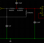
Actually if you change the 1.5nf to 2.2nf & the 4k3 to 3k9 the fr = -3db @ 20Hz & -3db @ 27kHz. The outputs will be @ 245mV RMS for 775mV RMS input.
Input impedance/resistance = 5.5k Ohms which won't be any problem being fed from a low output impedance/resistance of a mixer etc.
Input impedance/resistance = 5.5k Ohms which won't be any problem being fed from a low output impedance/resistance of a mixer etc.
Would there be any difference using the NE5532P vs TL071, since they're only being used at unity gain? I was given the impression there wouldn't.
Here's the spec for the mixer, which I got today (otherwise I would have linked it at the start):
http://assets.peavey.com/literature/specs/116340_13036.pdf
The inserts don't seem to be described though. Note it is the inserts I'm using to tap, not the FX send/return, because that's needed for reverb etc. to the front house speakers. I think what makes me nervous is knowing that when I simply linked the recorder onto the tap without any circuitry, the desk volume dropped significantly enough to no longer be putting enough out to the speakers, and the recorder inputs are "consumer line level unbalanced".
The inserts break the circuit when in use, so I'm shorting the send and return line on the jack to send the signal back to the desk, and tapping it. From the spec, I'm guessing it's probably a 600ohm out, 10k in, impedance. Is there a way I can test/measure that? I have a reasonable multimeter.
Please forgive me for being slow... is my thinking correct?
The attenuation is an L-Pad, using the 8.2k as series and the 4.3k as shunt.
The 1nF and 4.3k make up a low pass filter. I'm a little confused that the RC calc I'm using says it's 37kHz, not 56kHz, but even so, anything under that goes to the OpAmp, anything above that goes to ground (-3b/octave slope?). When I tapped 1.5nF in though, it came out at the 25kHz.
I should be ignoring "don't use X7R dialectric" type advice for this circuit, because it wont really have a noticeable difference in this application. I've got some of these in my box of bits - they'd be fine?
"Kemet R75 1μF Polypropylene Film Capacitor 90 V ac, 160 V dc ±5%"
Presumably resistor types are equally irrelevant - the box of "Metal Film 1/4W 1%" would be perfectly ok?
(It's a shame there's no quick-reference for caps and resistor types, and what they're used for - there are so many types!)
Input impedance/resistance = 5.5k Ohms
How do you calculate that figure? The closest I got was (8.2k + 3.9k)/2, but that's not correct, and I can't make sense of it.
The difference between using the NE5532P vs TL071, is in the self noise. NE's are Bipolar input devices & generally produce less noise with low to medium input resistance. Whereas TL's are Fet input devices, & generally produce more noise with low to medium input resistance. The opposite is generally true for both types. I say "generally" in both instances, because there are exceptions. With my circuits input the NE's should produce less noise. It's not a massive difference, & you probably wont notice, so it's up to you !
I'm wondering what the recorders input impedances are ? If they are low, which would be a surprise, then that could account for the drop in level. Anyway, with the 51R output imp. of this circuit, it won't be an issue.
The inserts Are probably a 600R out, 10k in, impedance. Based on the other In's/Out's in the PDF. I wouldn't worry about testing them, due to the PDF. You could always phone/email PV & ask !
You're not being slow ! Everybody has to learn, & asking questions & researching etc is how to. I still am & do.
Yes you're correct, the attenuation is an L-Pad, using the 8.2k as series and the 4.3k as shunt.
I reworked the L-Pad & filter values, as you've seen. The LPF is actually the 8.2k & 2.2nf. It's a -6db/octave slope. The -3db knee = 27kHz.
Don't ignore "don't use X7R dialectric" type advice for this circuit. Those Polypropylene Capacitors would be fine as you've already got them. Larger physically than needed though. The caps only need to be 16V DC or above.
Metal Film 1/4W 1% would indeed be perfectly ok.
Polystyrene/Polypropylene/Polycarbonate in that order, are what i use for filters. The tighter the tolerance the better. & Polycarbonate/Polyester/Ceramic for bypassing etc. Good quality Electrolytic are ok for input/output & power supply.
I calculated the Input impedance/resistance = 5.5k Ohms as follows. ( 8.2k + 3.9k = 12.1k ) Then ( 12.1k + 10k = 22.1k ) Then ( 12.1k x 10k = 121k ) Then ( 121k/22.1k = 5.47k ) = Near enough 5.5k for our purpose, so i didn't bother to quote 5.47k. It's a sum & product equation of all 3. Formula = Rtotal = R1×R2/(R1+R2) R2 = 8.2k + 3.9k
Thank you so much for explaining. I will get there!
I've got a lot of electrolytics, but they're fairly high values - 10uF, 47uF, 100uF, 470uF, 1000uF. It was a "getting started" pack, the same as the resistors. Good for smoothing out power supplies when I use PIC controllers though!
I've got a lot of electrolytics, but they're fairly high values - 10uF, 47uF, 100uF, 470uF, 1000uF. It was a "getting started" pack, the same as the resistors. Good for smoothing out power supplies when I use PIC controllers though!
Input impedance on the recording interface is supposedly 10k, although some who have it seem to say it can vary on inputs down to 5k. It's a great sounding recorder, but quality control on the chip selection was a bit hit and miss. It uses AKM AK4524 ADC/DAC chips, but rather bafflingly they have not made the gain adjustment on the inputs available, and set them all to a preconfigured level that corresponds to consumer line level.
There's a whole thread about 1200 posts long from years ago where people are trying to figure out why. The impedance can vary between 5k and 10k, but it varies uniformly across inputs, so it's not as if one pair of inputs are higher than another (at least, not by much), but the same interface can vary impedance depending on what it's attached to. The consensus seemed to be that as it's a "bus powered device" it varies with the power supply.
Either way, as you say, I'm good to go - time to sketch out a layout and break out the strip board!
Either way, as you say, I'm good to go - time to sketch out a layout and break out the strip board!
Hi, just a quick minor update for you. I've relocated one leg of the 3k9's from actual common, to virtual common. It won't any difference to the sound, but it's preferable as far as the DC voltages @ the OpAmps inputs/outputs are concerned. If you've already soldered them in place, it won't be a major job to change the positions ! Depending on your layout, it might just mean track cuts & links for each 3k9.
Everything else remains as before.
Everything else remains as before.
Attachments
- Status
- This old topic is closed. If you want to reopen this topic, contact a moderator using the "Report Post" button.
- Home
- Source & Line
- Analog Line Level
- Capacitor and Resistor choice for OpAmp line tap