Hi there,
MOS-based cap multipliers gain in popularity, but they have one rather serious drawback: along with the ripple, they also eat a substantial amount of good DC voltage that could be used for more productive purposes than generating heat.
Here is a first possibility to improve matters:
The idea is to generate a small auxiliary supply with C3, D6, D7, C4 to drive the gate at a sufficiently high voltage wrt. the source.
What is "sufficient"?
It depends on the MOS characteristics, the supplied current, the direction of the wind, but also the minimum voltage seen at the drain.
This circuit takes into account the latter, by locking the drive voltage to the bottom of the ripple valleys, thanks to D8 and C5.
D9 and R3 then shift this voltage by a "reasonable" amount to drive the MOS.
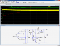
You have to decide what that reasonable amount is, but when it's done (correctly), the circuit will automatically adapt to the input voltage/ripple, which is a small, but non-negligible improvement over the plain-vanilla version, in addition to the lower dropout voltage (yellow trace is the raw input voltage).
Next, we will see how to go a bit further with moderate complications.
MOS-based cap multipliers gain in popularity, but they have one rather serious drawback: along with the ripple, they also eat a substantial amount of good DC voltage that could be used for more productive purposes than generating heat.
Here is a first possibility to improve matters:
The idea is to generate a small auxiliary supply with C3, D6, D7, C4 to drive the gate at a sufficiently high voltage wrt. the source.
What is "sufficient"?
It depends on the MOS characteristics, the supplied current, the direction of the wind, but also the minimum voltage seen at the drain.
This circuit takes into account the latter, by locking the drive voltage to the bottom of the ripple valleys, thanks to D8 and C5.
D9 and R3 then shift this voltage by a "reasonable" amount to drive the MOS.
You have to decide what that reasonable amount is, but when it's done (correctly), the circuit will automatically adapt to the input voltage/ripple, which is a small, but non-negligible improvement over the plain-vanilla version, in addition to the lower dropout voltage (yellow trace is the raw input voltage).
Next, we will see how to go a bit further with moderate complications.
Attachments
Hi there,
MOS-based cap multipliers gain in popularity, but they have one rather serious drawback: along with the ripple, they also eat a substantial amount of good DC voltage that could be used for more productive purposes than generating heat.
Here is a first possibility to improve matters:
The idea is to generate a small auxiliary supply with C3, D6, D7, C4 to drive the gate at a sufficiently high voltage wrt. the source.
What is "sufficient"?
It depends on the MOS characteristics, the supplied current, the direction of the wind, but also the minimum voltage seen at the drain.
This circuit takes into account the latter, by locking the drive voltage to the bottom of the ripple valleys, thanks to D8 and C5.
D9 and R3 then shift this voltage by a "reasonable" amount to drive the MOS.
You have to decide what that reasonable amount is, but when it's done (correctly), the circuit will automatically adapt to the input voltage/ripple, which is a small, but non-negligible improvement over the plain-vanilla version, in addition to the lower dropout voltage (yellow trace is the raw input voltage).
Next, we will see how to go a bit further with moderate complications.
I know that you are full of good ideas. I was thinking in similar direction, but haven't implemented it yet, it's a shame to lose so much good voltage on a output mosfet.
Why not replace D9 with a 4 volt zener diode in parallel with a potentiometer? Now you've got 4 volts of adjustment range to deal with even the highest threshold voltage MOSFETs, and you've got an explicit knob that lets you dial up whatever dropout voltage you dare.
Attachments
Elvee,
Any opinion on this arrangement:
I built an example of this and found it works quite well. Operating the MOSFETs common source instead of as a follower let's you get arbitrarily close to the rail you are filtering, within the limits set by the magnitude of the ripple.
Any opinion on this arrangement:
I built an example of this and found it works quite well. Operating the MOSFETs common source instead of as a follower let's you get arbitrarily close to the rail you are filtering, within the limits set by the magnitude of the ripple.
Elvee, for the first post, can you show some transient responses say for step load and step mains. The gate reference voltage is nicely clamped to the min of the raw ripple voltage, being directly pulled down if the raw ripple voltage sagged, but what does the recovery look like when load is reduced.
Can you indicate what increase in raw pk-pk ripple voltage is supportable.
I had a look at ripple reduction for HV high ripple situations, such as in old valve amps, and similarly took the path of generating an accessory supply rail that sits on top of the raw input voltage, but that didn't use a cap multiplier configuration. But your technique for clamping to the min of the raw ripple waveform is great, and I will check that out")
http://www.diyaudio.com/forums/power-supplies/280061-b-ripple-filler-filtering.html
Can you indicate what increase in raw pk-pk ripple voltage is supportable.
I had a look at ripple reduction for HV high ripple situations, such as in old valve amps, and similarly took the path of generating an accessory supply rail that sits on top of the raw input voltage, but that didn't use a cap multiplier configuration. But your technique for clamping to the min of the raw ripple waveform is great, and I will check that out
http://www.diyaudio.com/forums/power-supplies/280061-b-ripple-filler-filtering.html
Last edited:
diyAudio contributor, Keantoken, has developed a cap-multiplier alternative he calls the K-multiplier. He's lists a dropout voltage of only 1.8V, not to mention other specifications which are significantly superior to those of an an standard cap-multiplier.
The K Multiplier
The K Multiplier
I started the Easy Peasy Cap Multiplier thread because for some reason had a hard time with these other designs to work. I tried building the K multiplier, I tried one from ESP's website - it did not work for me. Circuit is more difficult tha appears. The MOSFET one by Juma, although loses 4v, works splendidly and is easy. No PCB needed - just solder onto the legs of one MOSFET - and a few resistors and caps.
http://www.diyaudio.com/forums/solid-state/297921-jumas-easy-peasy-capacitance-multiplier.html

Ripple went from 20mV down to sub mV at 1.5amps current draw. Perfect for a class A amp as the PSU line hum went away completely.
If you have a few volts to burn (like if you have a 15vac trafo and need 15vdc - this is perfect.
http://www.diyaudio.com/forums/solid-state/297921-jumas-easy-peasy-capacitance-multiplier.html
Ripple went from 20mV down to sub mV at 1.5amps current draw. Perfect for a class A amp as the PSU line hum went away completely.
If you have a few volts to burn (like if you have a 15vac trafo and need 15vdc - this is perfect.
Elvee,
Any opinion on this arrangement:
I built an example of this and found it works quite well. Operating the MOSFETs common source instead of as a follower let's you get arbitrarily close to the rail you are filtering, within the limits set by the magnitude of the ripple.
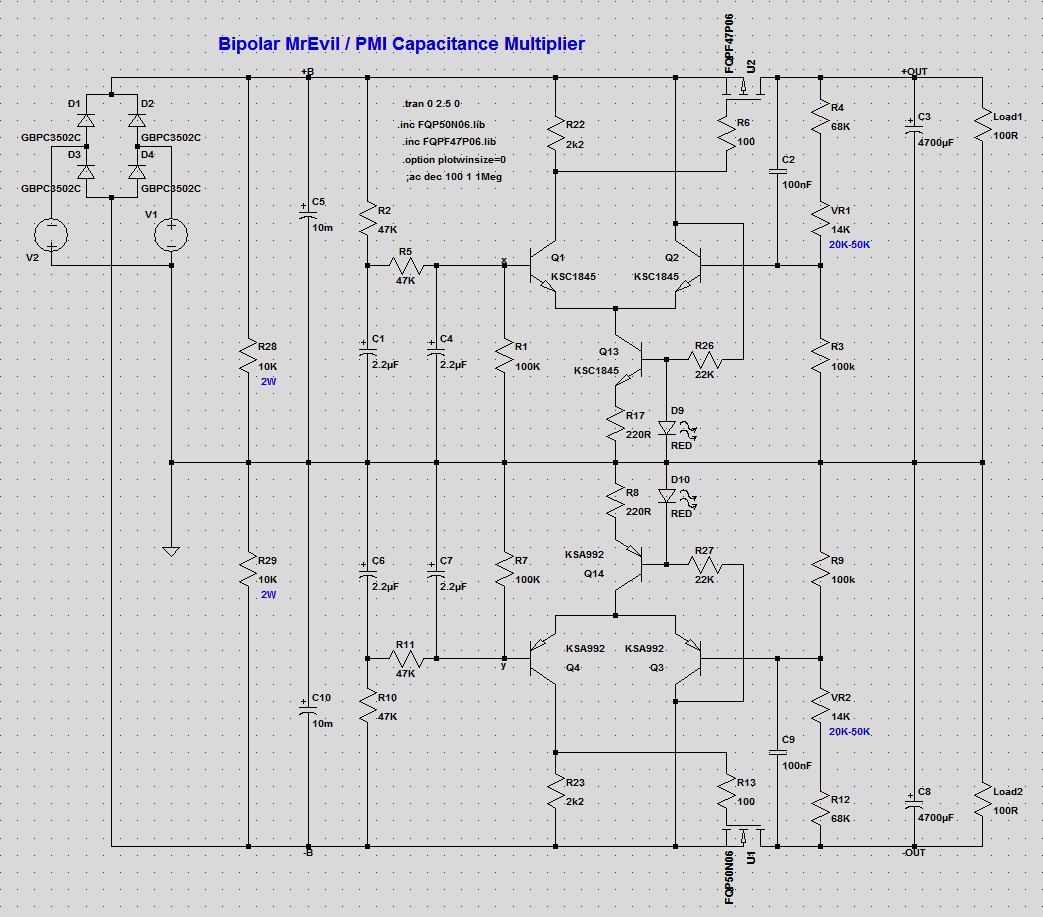
This is my mosfet PS regulator, with protections.
Attachments
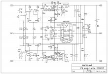
Post #8 isn't exactly what I would call a "regulator" since its DC transfer characteristic is
Here's how it works
R1+R2+R27 apply (0.4231 * Vin) to the reference input of the error amplifier.
R22+R26 apply (0.4735 * Vout) to the feedback input of the error amplifier.
Negative feedback works to make these two voltages identical, thus
- Vout = 0.8935 * Vin
Here's how it works
R1+R2+R27 apply (0.4231 * Vin) to the reference input of the error amplifier.
R22+R26 apply (0.4735 * Vout) to the feedback input of the error amplifier.
Negative feedback works to make these two voltages identical, thus
- 0.4231 * Vin = 0.4735 * Vout
- Vout/Vin = (0.4231 / 0.4735) = 0.8935
Post #8 isn't exactly what I would call a "regulator" since its DC transfer characteristic isIf the input is 20 volts, the output is 17.9 volts. If the input is 35 volts, the output is 31.3 volts. That's not exactly what I call a voltage "regulator".
- Vout = 0.8935 * Vin
Here's how it works
R1+R2+R27 apply (0.4231 * Vin) to the reference input of the error amplifier.
R22+R26 apply (0.4735 * Vout) to the feedback input of the error amplifier.
Negative feedback works to make these two voltages identical, thus
- 0.4231 * Vin = 0.4735 * Vout
- Vout/Vin = (0.4231 / 0.4735) = 0.8935
That's why I put it here with a cap multipliers(this is no classic one), but why not call it regulator, it regulates. I my country we call regulator with fixed output voltage stabilizator.
As the title implies, these are just ideas, not a fully specified, ready to build project; the end user is free to select whatever minutes details he incorporates, including the reference voltageWhy not replace D9 with a 4 volt zener diode in parallel with a potentiometer? Now you've got 4 volts of adjustment range to deal with even the highest threshold voltage MOSFETs, and you've got an explicit knob that lets you dial up whatever dropout voltage you dare.
I wouldn't classify this as a simple cap-multiplier, as it incorporates a global FB loop.Elvee,
Any opinion on this arrangement:
I built an example of this and found it works quite well. Operating the MOSFETs common source instead of as a follower let's you get arbitrarily close to the rail you are filtering, within the limits set by the magnitude of the ripple.
I would call it a reference-less regulator or something of the kind
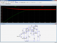
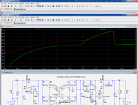
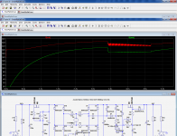
The transient behavior for line and load steps is rather disgraceful, see pic 1 and 2, with an ordinary multiplier for comparison: after an input voltage decrease or a load increase, the function is lost for some time.Elvee, for the first post, can you show some transient responses say for step load and step mains. The gate reference voltage is nicely clamped to the min of the raw ripple voltage, being directly pulled down if the raw ripple voltage sagged, but what does the recovery look like when load is reduced.
Can you indicate what increase in raw pk-pk ripple voltage is supportable.
I had a look at ripple reduction for HV high ripple situations, such as in old valve amps, and similarly took the path of generating an accessory supply rail that sits on top of the raw input voltage, but that didn't use a cap multiplier configuration. But your technique for clamping to the min of the raw ripple waveform is great, and I will check that out
http://www.diyaudio.com/forums/power-supplies/280061-b-ripple-filler-filtering.html
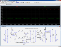
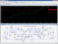
Fortunately, the remedy is extremely simple: add a diode (D15) across the filter's resistance, see pic 3 and 4.
Regarding the max ripple input, the limit is common sense: if we reduce the main filter cap by a factor 10, to 1000µF, the behavior remains normal: although it still manages to remain ~2V above the regular type, its output ripple is somewhat cleaner: pic 5
I agreeThat's why I put it here with a cap multipliers(this is no classic one), but why not call it regulator, it regulates. I my country we call regulator with fixed output voltage stabilizator.
Let's examine the next step: the way the dropout was defined is not very practical, and directly imposing a minimum, deterministic dropout by design would be more convenient.
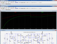
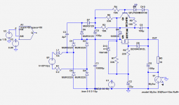
That can be done with a single additional transistor, see pic 6:
Here, the troughs of the I-O waveform are sampled by C5 D8, and the resulting value is compared to a reference, again a LED (but other options are possible) by transistor Q1, which in turn steers the multiplier's filter.
This eliminates lots of unknowns from the equation.
At first sight, one would think that with so many components straddling the I-O space, the performance would be degraded, as they leak corrupted input voltage into the output.
In fact, the opposite happens: the main performance limitation of simple, non-GNFB cap multipliers stems from the output conductance of the active device, caused by the Early effect for BJT's or the channel length modulation for FETs.
Additional components in parallel with the output should in principle compound these effects, but here, the active circuitry provides a raw, first-order compensation of these effects, in a similar (but cruder) way as the one outlined here:
http://www.diyaudio.com/forums/power-supplies/269229-improving-capacitance-multipliers.html
The waveform at the collector of Q1, after integration by the filter R7 C2 mimics the effect of the ripple, but with an opposite phase.
This trick provides a 2~3 fold improvement over the physical floor imposed by the active device; not very much, but not to be scorned.
Attachments
Last edited:
If you want tremendous ripple rejection with very little voltage drop (hence very little power dissipation), build a series cascade of N>1 depletion mode MOSFET capacitance multipliers, and set their gate bias voltages very carefully. Each one gives you X dB of ripple rejection so the cascade with N of them in series gives you N*X dB of ripple rejection. By careful selection of gate bias voltage you can drop as little as 200mV per stage.
Digi-Key US has 131 different depletion mode MOSFETs in stock and on the shelf: link
Digi-Key US has 131 different depletion mode MOSFETs in stock and on the shelf: link
If you want tremendous ripple rejection with very little voltage drop (hence very little power dissipation), build a series cascade of N>1 depletion mode MOSFET capacitance multipliers, and set their gate bias voltages very carefully. Each one gives you X dB of ripple rejection so the cascade with N of them in series gives you N*X dB of ripple rejection. By careful selection of gate bias voltage you can drop as little as 200mV per stage.
Digi-Key US has 131 different depletion mode MOSFETs in stock and on the shelf: link
There is no depletion mode mosfet powerful enough to make cap multiplier for power amp, and no p channel that I know.
I use this one in every day life http://www.diyaudio.com/forums/powe...ply-cap-multiplier-electronic-protection.html and here is practical example http://www.diyaudio.com/forums/solid-state/182554-thermaltrak-tmc-amp-22.html#post3907062
Yes I was chatting with another diyA member at Burning Amp yesterday, a guy who has been on the site for a lot more years than me. He observed that a surprisingly large number of members appear to want something they can buy, solder together, and listen to without ever making a single adjustment, measurement, part selection, or alignment. A Heathkit in other words. It reminded me of this famous story. I suspect he might be more right than wrong.
Mark Johnson
I'll accept your polite reprimand but in my defense and in the defense of other hobbyists like me, who;
1. choose to allocate their time in a way that doesn't waste it on less impactful outcomes.
2. don't wish to wade in waters much deeper than their equipment can fathom.
Try not to resent us for our limitations or our preferences and try to avoid posturing moral superiority by characterizing us as mindless freeloaders. All of us are useful to the audio community, even the least of us provide the designers here with real world research feedback.
Recent amp submissions are getting really good PSRR numbers so forgive me for preferring to focus on learning those instead of a topology that will yield far less benefit.
Last edited:
- Status
- This old topic is closed. If you want to reopen this topic, contact a moderator using the "Report Post" button.
- Home
- Amplifiers
- Power Supplies
- Cap-mult improvements ideas