
A speaker will never be able to reproduce square wave. Regardless rise time and time delay, speaker's impulse/square response will always be oscillating.
PMA said:A speaker will never be able to reproduce square wave. Regardless rise time and time delay, speaker's impulse/square response will always be oscillating.
If you want to get technical, nothing can reproduce a real square wave which only exists as a mathematical construct. The idea is to get the speaker as close to reproducing a square wave as possible.
dave
Look at the equivalent circuit of the speaker (can be seen for example on Rod Elliot's pages). The speaker's equivalent circuit comprises a RLC resonant circuit which substitutes mechanical behavior of the membrane. In series there is a coil resistivity and inductance. The membrane's response for square wave is oscillating (damped oscillations).
ok, I'm in for trying to accomplish the unachiefable (an approximation).
1. as mentioned by dave, the lesser components, the lesser phase inaccuracies, so only 1, max 2-way system.If 2-way we look for at least a smooth phase turn (none if possible).
2. I propose to look for a system that can look forward for steep rises an compensate moving membrane inerty by overboost and produce a counter-emf for braking before the cone shoots out to the opposite wall.(it will be a lotus elise, no corvette)
3. 40000 watts amps to accomplish this will cost a fortune, so we will look for a cone as light as possible. Since I feel we will end up with a dsp-progam, straight frequency-response is not of our primary concerns, fast impuls response is.(again, no viper, but yes, a kawahondasuzuki 600 fzzrxs fireblade, aggressive peaking power, not a smooth gold wing)
4. haa, initially fast impuls response, thus we are looking for horn loaded drivers. Lightest ultimately is a horn-loaded plasma tweeter wich should be rejected because of too high cross-over point (unless you rebuild the one on NP's picture).
Feasable things are a horn-loaded ESL's or a traditional driver+horn.
Why a horn?
because it's the most optimal resistance for a moving membrane.
A well-designed horn (tractrix) creates the most evenly spread air-transformation-resistance you can imagine, dixit it's high efficiency. High efficiency means less membrane motion, means less counter-emf to coop with.
For the horn-loaded ESL we've got a problem (bipolar) wich can be solved by installing a mirrored system in the next room, phase opposed, but no harm as long as doors are closed.(cost-saving: 1 driver = 2 systems)
A traditional driver has to be as light as possibel. Problem is most of them are build to achieve high SPL's, so they are build too heavy, and have therefore a smaller bandwidth. We are looking for pro gear for home use: 2 or 3 watt will be sufficient at an efficiency of 108-112 dB/W/m. So please Mr Harman Kardon or Mr Pioneer, make them thinner and lighter (and faster).
just my 1 cent yet, others may follow.
planet10 said:
If you want to get technical, nothing can reproduce a real square wave which only exists as a mathematical construct. The idea is to get the speaker as close to reproducing a square wave as possible.
dave
Finally someone that agrees with me! Thanks planet10 - I have a feeling mrfeedback just likes to argue with me sometimes 🙄
I too say it's impossible - simple physics
Good news on the square wave
Hello again everybody!
First thanks to all for the flowers regarding my previous post🙂 🙂
As my hand clap test has been quite a time ago and because I couldn`t remember well anymore, I have repeated my hand clap experiment today with a Sennheiser condenser measurement mic. with preamp and a small scope and guess what ... sometimes I can get two cycles of an even almost perfect square with about 1ms flat top and bottom of the waveform. It´s really a pity that my other Tek scope with storage capabilities do not work at present otherwise I could have presented You a nice screen shot from the waveform.
I always had the impression that applause is particular difficult to reproduce naturally sounding by speakers. Mostly it sound like rain drops on sheet metal roof but never really like what it should.
Anybody here ever made similar experiance?
Bill:
I highly appriciate Your efforts for the "Square Wave Project" and for sure I`ll follow this very closely and try to contribute where I can!
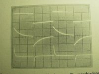
Your active bandpass setup is a very good idea but I guess the output is predictable and it will look pretty similar to the center waveform shown at the pic. below unless the rising (and falling) edge of the wave will not be so fast due to the 20kHz lowpass (the rise time can be calculated but I`m to lazy to grab the formulas now).
Though this wave at the first glance does not look like a perfect square wave at all, we could be more than happy if we were to achieve this as ouput from a real life speaker only to some extend. To stay realistic I think more than this we can not ask for but it would be already much better than usual speaker outputs.
Eric:
of course You`re right that unless an explosion or something like that there is no acoustical sensation that can maintain constant sound pressure for substantial periods.
But the hand clap test proofs that there is for shorter periods and maybe we find more examples.
Rodd:
As the perfect time response filters due to their nature do not allow steep crossover sloopes I second Your concerns about IM.
But if You refer to Charles`s thread about "Active Subtractive XOs" You can see that it is possible to implement the second order xovers for the highpass and leave the hump and the slow drop section of this xovers to the woofer respectively the mid(full)range (in a 3 way design) . Hence a true (no hump) 2.order highpass should be sufficient to control the IM issue just like it does in traditional designs (preassumed resonable done of course).
Therefore I´m not sure if Charles`s new approuch, the "advanced filler driver XO" how he calls it, actually has advantages over the "ordinary" electronic filler driver XO which can be seen as the second block diagramm in the link he posted
just recently. I tend to favour this one over the other two new designs further below in the link (but it might be that I have not yet understood the new ones completly - I still have to think about).
lieven:
The "perfect" transient respond speaker approximation design has nothing at all to do with the need for 40000W amps, ultralightweight diaphragms, horn-loaded ESL's, less membrane motion or 108-112 dB/W/m efficiency drivers - "just" some suitable "ordinary" drivers (as for instance as Dave stated about FR cones - in particular I think about the Jordans or Fostex) and a clever Xover concept which will be the heart of all this.
Hello again everybody!
First thanks to all for the flowers regarding my previous post🙂 🙂
As my hand clap test has been quite a time ago and because I couldn`t remember well anymore, I have repeated my hand clap experiment today with a Sennheiser condenser measurement mic. with preamp and a small scope and guess what ... sometimes I can get two cycles of an even almost perfect square with about 1ms flat top and bottom of the waveform. It´s really a pity that my other Tek scope with storage capabilities do not work at present otherwise I could have presented You a nice screen shot from the waveform.
I always had the impression that applause is particular difficult to reproduce naturally sounding by speakers. Mostly it sound like rain drops on sheet metal roof but never really like what it should.
Anybody here ever made similar experiance?
Bill:
I highly appriciate Your efforts for the "Square Wave Project" and for sure I`ll follow this very closely and try to contribute where I can!
Your active bandpass setup is a very good idea but I guess the output is predictable and it will look pretty similar to the center waveform shown at the pic. below unless the rising (and falling) edge of the wave will not be so fast due to the 20kHz lowpass (the rise time can be calculated but I`m to lazy to grab the formulas now).
Though this wave at the first glance does not look like a perfect square wave at all, we could be more than happy if we were to achieve this as ouput from a real life speaker only to some extend. To stay realistic I think more than this we can not ask for but it would be already much better than usual speaker outputs.
Eric:
of course You`re right that unless an explosion or something like that there is no acoustical sensation that can maintain constant sound pressure for substantial periods.
But the hand clap test proofs that there is for shorter periods and maybe we find more examples.
Rodd:
As the perfect time response filters due to their nature do not allow steep crossover sloopes I second Your concerns about IM.
But if You refer to Charles`s thread about "Active Subtractive XOs" You can see that it is possible to implement the second order xovers for the highpass and leave the hump and the slow drop section of this xovers to the woofer respectively the mid(full)range (in a 3 way design) . Hence a true (no hump) 2.order highpass should be sufficient to control the IM issue just like it does in traditional designs (preassumed resonable done of course).
Therefore I´m not sure if Charles`s new approuch, the "advanced filler driver XO" how he calls it, actually has advantages over the "ordinary" electronic filler driver XO which can be seen as the second block diagramm in the link he posted
just recently. I tend to favour this one over the other two new designs further below in the link (but it might be that I have not yet understood the new ones completly - I still have to think about).
lieven:
The "perfect" transient respond speaker approximation design has nothing at all to do with the need for 40000W amps, ultralightweight diaphragms, horn-loaded ESL's, less membrane motion or 108-112 dB/W/m efficiency drivers - "just" some suitable "ordinary" drivers (as for instance as Dave stated about FR cones - in particular I think about the Jordans or Fostex) and a clever Xover concept which will be the heart of all this.
Attachments
lieven said:1. as mentioned by dave, the lesser components, the lesser phase inaccuracies, so only 1, max 2-way system.If 2-way we look for at least a smooth phase turn (none if possible).
4. haa, initially fast impuls response, thus we are looking for horn loaded drivers. Lightest ultimately is a horn-loaded plasma tweeter wich should be rejected because of too high cross-over point (unless you rebuild the one on NP's picture).
Feasable things are a horn-loaded ESL's or a traditional driver+horn.
Unfortuneatly these 2 are contradictory since a horn can only cover 3 or 4 octaves, which means at least a 3-way system.
For the horn-loaded ESL we've got a problem (bipolar) wich can be solved by installing a mirrored system in the next room, phase opposed, but no harm as long as doors are closed.(cost-saving: 1 driver = 2 systems)
(Note: an ESL is a dipole not a bipole) I actually have drawings of just such a system -- the ideal backload for a horn is an identical horn and have toyed with the idea of mounting my ESLs in the wall.
dave
"Also with regards to seeing a square wave on a scope - this would be a trapezium possibly even if the input signal was a square wave as the scope is not perfect (i.e. doesn't have a sampling rate of infinity!)
Also with regards to seeing a square wave on a scope - this would be a trapezium possibly even if the input signal was a square wave as the scope is not perfect (i.e. doesn't have a sampling rate of infinity!)"
annex666, not argueing with you, just pointing out some facts - have you ever used a CRO ?.
Ummm, also I think I was the first here to say that reproducing a LF square wave is impossible.
I think that we agree that there are no actual LF square wave sources, but higher up the scale there are and we need to establish a realistic frequency for the square wave fundamental, and then the rest of the design can fall into place.
Eric.
dave, you're right, it's a dipole.
cocolino, youre handclapping is just a amplified clipping pre-amp 'sound'. You can't possibly make a constant linear increasing pressure-wave with your hands during no matter what time, cause that's what you need. Even if constant pressure during some period, membrane of mike wil tend to go back to rest position because of equalling pressure (result would be kind of triangle wave).
If you record the pressure IN a room under pressure, you will only notice the increase in pressure (ears in a plane) once pressure is constant, everthing settles to normal. Only comparing (measuring) to the outside world will give a square.
and transient response is all about lightweight drivers!!!
Hi Christoph (Cocolino)
Maybe I wasn't clear enough to state what the advantages of the subtractively derived filler driver channel is.
Apart from the fact that you need only two filters (1HPF & 1 LPF) and that it is less prone to tolerances, it's main advantage is that you can use the midrange over a larger frequency range compared to the original filler driver approach.
I will post some simulation results so everyone can see. Apart from this: If that type of crossover couldn't be implemented in subtractive form, I hadn't posted it under the subtractive thread.
Regards
Charles
Hi all
Before someone else joins in just to tell us that in real life neither a speaker will ever be able to reproduce a squarewave nor would real sqarewaves exist :
=> I assume everybody agrees on both !
But we have to agree as well, how a realistic squarewave-response of a loudspeaker should look like.
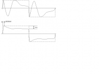
I enclosed a drawing with two diagrams:
The upper one shows how an ordinary speaker (more than 95% of the speakers out there) would reproduce a squarewave: It is simply the lineup of the different driver's step responses.
The second one shows what could be achieved with good engineering: An initial transient that isn't infinitely steep due to the finite upper cutoff frequency, but which could be made reasonably steep though. Due to the fact that the speaker doesn't go down to DC there is also decay following the transient, which is smaller the lower the LF cutoff frequency and the higher the signal frequenciy is. There will also be some inevitable transinent ringing, interference etc.
But I think it is evident wich one represents a rectangular MORE ACCURATELY, isn't it ?
Regards
Charles
Before someone else joins in just to tell us that in real life neither a speaker will ever be able to reproduce a squarewave nor would real sqarewaves exist :
=> I assume everybody agrees on both !
But we have to agree as well, how a realistic squarewave-response of a loudspeaker should look like.
I enclosed a drawing with two diagrams:
The upper one shows how an ordinary speaker (more than 95% of the speakers out there) would reproduce a squarewave: It is simply the lineup of the different driver's step responses.
The second one shows what could be achieved with good engineering: An initial transient that isn't infinitely steep due to the finite upper cutoff frequency, but which could be made reasonably steep though. Due to the fact that the speaker doesn't go down to DC there is also decay following the transient, which is smaller the lower the LF cutoff frequency and the higher the signal frequenciy is. There will also be some inevitable transinent ringing, interference etc.
But I think it is evident wich one represents a rectangular MORE ACCURATELY, isn't it ?
Regards
Charles
Attachments
It is definetely not a clipped pre-amp. sound. The output of the mic.preamp is about 0,8V peak to peak which is far from its overdrive level.cocolino, youre handclapping is just a amplified clipping pre-amp 'sound'. You can't possibly make a constant linear increasing pressure-wave with your hands during no matter what time, cause that's what you need. Even if constant pressure during some period, membrane of mike wil tend to go back to rest position because of equalling pressure (result would be kind of triangle wave).
Again: the scope has been set at the 500µs Time/div. range and under this conditions I was sometimes able (of course clapping hands can`t be done always equally) to get 1-2 cycles of a just nice looking square wave (around 10cm distance hands to mic).
I encourage everybody with access to a measurement mic. and a scope to try the same.
Of course the quality of the square is not like from a electronic square wave generator but the signal has very reasonable flat top and botton and in the 500µs/Time Div. range it looks indeed much more like a square than a triangle.
And also again:
as Eric stated first correctly and has repeatedly expressed by others as well, a perfect acoustical square does not exist (as it does not even in electronic if things taken to extremes) nor this is necessary in order to achieve some audible improvements over usual designs.
So please let`s stop to discuss this one again and again but let`s proceed with the next questions.
One is what can we achieve with a real world design under the most optimistic circumstances.
And I assume that most of us will agree that the shape of the wave must look like something what presented Charles above though IMHO the quite slow decay likely is a bit too optimistic assumption (supposed we use 30Hz square wave test signal according to Bill`s suggestion).
An ultrafast rise time, though desirable is not the first priority of the square wave approximation in this design.
Due to the reasons already mentioned namely that low frequency constant pressure waves don`t exist and additionally that our ears are less sensitive to perception of time distortion towards lower frequency, trying to extremely delaying the pressure drop decay also is not first priority IMHO.
The no.1 issue as I see it, is a as coherent and even as possible shape after the leading edge until a still to determine point after which further trying to maintain the pressure do not bring much more audible improvement.
Charles: It might perfectly be that I just not yet got it completly. BTW: You do a great job about the Active Subtractive XOs!!!Maybe I wasn't clear enough to state what the advantages of the subtractively derived filler driver channel is.
As far I understand (if at all) your schematic of the advanced filler driver XO by now , as You split the derived filler driver response and partially add it to the highpass as well this introduces two humps, one in the lowpass and the other in the highpass. If this is the case my concerns about IM (in the tweeter repectively the higher frequency driver) with this approuch are not so erroneous and distortion in the high driver might better be controlled by use of the version that do not produce a hump in the highpass section at all but in the lowpass only (and which is also derived through substraction). Just to avoid misunderstanding: in case of a TWO-WAY filler system, I refer to the 2 drivers design with substractive filler driver XO (where the midrange is added into the woofer response, what cause the hump) not the 2way 3 driver system where there is the third driver in order to fill the notch.
Do I still miss something

Hi Christoph
NOW I see WHERE we are diverging ! 🙂
I do of course agree with you that ALL versions of a phase- accurate 2nd order crossover with humps (i.e. the "advanced filler driver", 2nd order with overlap & EQ and the cascaded subtractive crossover), are a little inferior to ordinary 2nd order crossovers or the ordinary filler driver crossover, regarding tweeter IMD (in the end, everything is a compromise).
But they should still be better in this respect than first order crossovers or using an ordinary subtractive crossover in a disadvantageous fashion (that was at least my intention when I started to stress my brain).
What I was talking about, was the use of the third diagram (active subtractivce thread, filler driver posting), to not only generate a filler driver channel by leaving the HPF and LPF cutoff frequency the same, but rather move the HPF cutoff frequency higher and move the LPF cutoff frequency lower. Now we DON'T add the subtractively derived signal to our woofer and tweeter channel as it is shown on the 4th diagram:
=> We use it to drive a midrange driver over a wider frequency range than we would use it with the "ordinary" filler driver crossover !
Now we definitely get better tweeter IMD and woofer FMD than a two-way or an ordinary filler driver setup could achieve (at least theoretically). The transfer function of this midrange channel has only 6 dB/octave slopes and two humps, one at the lower and one at the upper end (look at the simulation results within my last post in the subtractive thread). It is therfore a good idea to use a fullrange driver for this purpose, which in this case doesn't have to be one of the real fancy, expensive kind (we shouldn't forget that many GOOD fullranges make EXCELLENT midranges).
Regards
Charles
P.S.: Maybe I should think about decent names for the third and the forth arrangement so we are always talking about the same thing.
- Status
- Not open for further replies.
- Home
- Loudspeakers
- Multi-Way
- Can't Reproduce a Square Wave.