this is the option too, Pioneer Super Linear Circuit, reaches power 2MHz:
https://www.diyaudio.com/community/threads/the-pioneer-super-linear-circuit.313163/
https://www.diyaudio.com/community/threads/the-pioneer-super-linear-circuit.313163/
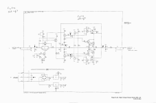
here you have Pioneer circuit cascoded, RIAA correction should be ommited, with proper transistors you should get BW>2MHz

Thanks for all the leads: I'll have some work testing all of them, in isolation or combination.
Regarding the distortion of the input stage, in its environment, it is ~4ppm. A bit high to my taste, but a very minor contributor with my current options.
I don't intend to include everything in a GNFB, it would be too demanding. Having individual blocks with a low enough THD looks more sensible
Regarding the distortion of the input stage, in its environment, it is ~4ppm. A bit high to my taste, but a very minor contributor with my current options.
I don't intend to include everything in a GNFB, it would be too demanding. Having individual blocks with a low enough THD looks more sensible
It could be 50ohm; in fact an inverting topology with a 50R input resistor could eliminate a number of distortions, but I don't see how to implement it in an effective wayWhat is the input impedance you need? 50 Ohms?
Almost, but not quite: the output voltage is a bit limited with a 40V supplyMaybe a ADA4780 chip amp would do the trick?
The Pioneer circuit seems to use regenerative bias on the input diamond, which is something I was going to suggest. I'm not sure how well it works at 1MHz? They also seem to be obsessed with reverse bias clamping diodes?here you have Pioneer circuit cascoded, RIAA correction should be ommited, with proper transistors you should get BW>2MHz
View attachment 1185820
The simulations I did were a bit better without Q15, Q16. And a tiny bit better with bypass caps on R3,R4. Other things that I though should help had unexpected results.They bootstrap (or cascode if you prefer) the output transistors: I have found that their Early effect is a major contributor to the THD
And from the PG508, it helps to cross couple the folded cascodes, caps between R9 and R10, and between R1 and R2.
maybe too much clamping...The Pioneer circuit seems to use regenerative bias on the input diamond, which is something I was going to suggest. I'm not sure how well it works at 1MHz? They also seem to be obsessed with reverse bias clamping diodes?
attached asc file for playing
cheers
Pawel
Attachments
Thanx but I don't have models for BF469 and BF470. Perhaps I could sub BD139/140? It would be great if you could share your models.
3325A HV amp Note the VI output protection that kills the VAS bias.
Attachments
Last edited:
Hi, you can use any HF TO126 device with high enough VCE and low capacitance,Thanx but I don't have models for BF469 and BF470. Perhaps I could sub BD139/140? It would be great if you could share your models.
.MODEL BF469 NPN(IS=7.974E-15 ISE=2.266E-16 ISC=4.33E-12 XTI=3
- BF=122 BR=6.235 IKF=0.01029 IKR=0.02746 XTB=1.5
- VAF=25.51 VAR=19.43 VJE=0.4581 VJC=0.197
- RE=0.3814 RC=0.439 RB=1 RBM=0.5 IRB=1E-06
- CJE=1.742E-11 CJC=5.045E-12 XCJC=0.1041 FC=0.8555
- NF=0.993 NR=0.999 NE=1.18 NC=1.397 MJE=0.3092 MJC=0.1947
- TF=7.073E-10 TR=1E-08 PTF=0 ITF=0.1495 VTF=6.144 XTF=289.5
- EG=1.11 KF=1E-9 AF=1 MFG=PHILIPS)
.MODEL BF470 PNP(IS=9.124E-15 ISE=1.672E-15 ISC=2.139E-13 XTI=3
- BF=198.2 BR=1.256 IKF=0.13 IKR=0.1 XTB=1.5
- VAF=465.9 VAR=13 VJE=0.8484 VJC=0.6298
- RE=0.635 RC=1.42 RB=5 RBM=0.5 IRB=1E-06
- CJE=1.447E-11 CJC=8.483E-12 XCJC=0.619 FC=0.99
- NF=0.9904 NR=0.99 NE=1.527 NC=1.08 MJE=0.3884 MJC=0.4561
- TF=1.38E-09 TR=1E-32 PTF=0 ITF=0.065 VTF=2 XTF=21.78
- EG=1.11 KF=1E-9 AF=1 MFG=PHILIPS)
anyway I found this circuitry has too much distortion @1MHz for Elvee's demands, and is little peaky at this frequency.
cheers
Pawel
PS for 1KHz it is excellent
I rechecked, and indeed with the current version, the transistors seem to do nothing.The simulations I did were a bit better without Q15, Q16. And a tiny bit better with bypass caps on R3,R4. Other things that I though should help had unexpected results.
Several iterations before, it provided a >4 fold improvement n THDi
Interesting, but unless I miss something the gain is unity3325A HV amp Note the VI output protection that kills the VAS bias.
I am still trying to improve my amplifiers, and the best candidate so far is the Groner-based one, but I am faced with a strange behaviour: when the compensation cap C1 is too small (12p), the THD is relatively good (0.003%), and logically the FR has a nasty peak due to insufficient margins.
If the cap is increased to 22p, the FR is ~flat, and the THD increases, which is to be expected. What is surprising is the magnitude: it shoots to 0.015%, a five-fold increase, when the cap value is not even doubled.
In addition, the circuit tolerates an output-inclusive scheme, which means that increasing the compensation should have a minimal effect on the THD.
Can someone explain that paradox?
Attachments

- Home
- Amplifiers
- Solid State
- Can you improve these amplifiers?