Hello svjeff --
Thank you for your input. This is new information for me. On your first point, I always thought the mark of a full differential or fully balanced device is that is has two discrete circuits (one + and one -) for each channel. And this is what my board has. Is this not accurate? Could it be you are thinking of a different board?
I also do not have an FR WOOF channel. I have SUB; WOOF; MID; and FR channels. Regarding where to pull the low frequencies from for the woofers in my 3-way speakers. I saw the equalization (that I do not want) that you mention happening in the SUB channel. That is one reason I picked the WOOF channel to drive my woofers. True, the WOOF channel does have a HI PASS section that I do not need, but my plan was to jumper over that. The other reason for using the WOOF channel is that I would like to reserve the SUB channel for some point in the future when I might want to add subs to my system.
Rob,
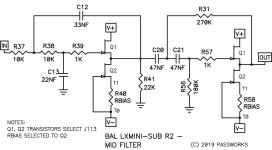
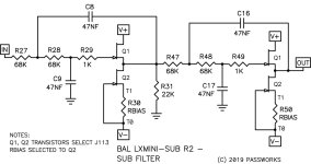
I was recalling from memory and incorrectly stated that the SUB channel is second order lowpass. Upon reviewing the earlier schematics (one of which I had posted) it is clear that the SUB channel is 4th order lowpass. The highpass in the MID channel is second order.
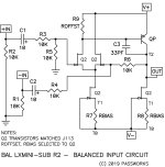
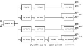
I found the block diagram, attached, which is a nice summary of the design. Notice that the differential circuits are at the input and the outputs. The crossover circuits are single ended. Your board, I have the same, has differential inputs and outputs but I don't think it is considered "fully differential."
I did not refer to a FR WOOF channel. There was a period after FR, but had I wrote FR channel it would have been clear. Sorry about that.
Another close look at the physical board, following the signal path, should reveal which capacitor is which. As Bill suggested, you are very close.
Jeff
I was recalling from memory and incorrectly stated that the SUB channel is second order lowpass. Upon reviewing the earlier schematics (one of which I had posted) it is clear that the SUB channel is 4th order lowpass. The highpass in the MID channel is second order.
I found the block diagram, attached, which is a nice summary of the design. Notice that the differential circuits are at the input and the outputs. The crossover circuits are single ended. Your board, I have the same, has differential inputs and outputs but I don't think it is considered "fully differential."
I did not refer to a FR WOOF channel. There was a period after FR, but had I wrote FR channel it would have been clear. Sorry about that.
Another close look at the physical board, following the signal path, should reveal which capacitor is which. As Bill suggested, you are very close.
Jeff
Attachments

Thank you for the images, Nelson. You had actually already provided these back in Post #17 of this thread. I also have the detective work that Bill (elwood625) has done. I also have worked with the online calculator to identify the values of C's and R's that are needed to achieve the 600Hz and 4kHz crossover frequencies I need. What is not known are the locations on the board where these C and R values should be plugged in.


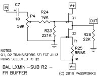
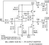
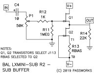
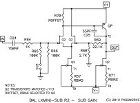
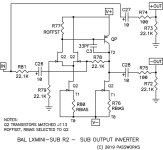
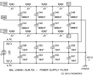
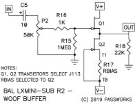
Here are schematics of various sub circuits.
Attachments
-
 BALANCED INPUT SCH.jpg241.2 KB · Views: 131
 -
 LX MINI +2 RESP.gif11.6 KB · Views: 137
 -
 BLOCK DIAGRAM.jpg119.8 KB · Views: 131
 -
 FR BUFFER.jpg192.6 KB · Views: 130
 -
 FR FILTER.jpg167.2 KB · Views: 129
 -
 FR OUTPUT INVERTER.jpg234.9 KB · Views: 128
 -
 MID BUFFER.jpg193.9 KB · Views: 129
 -
 MID FILTER.jpg155 KB · Views: 121
 -
 MID OUTPUT INVERTER.jpg237.9 KB · Views: 115
 -
 SUB BUFFER.jpg190.3 KB · Views: 122
 -
 SUB FILTER.jpg145.9 KB · Views: 119
 -
 SUB GAIN.jpg174.9 KB · Views: 114
 -
 SUB OUTPUT INVERTER.jpg233.3 KB · Views: 124
 -
 SUPPLY FILTER.jpg257.3 KB · Views: 122
 -
 WOOF BUFFER.jpg191.6 KB · Views: 133
Thank you Nelson. This will be VERY helpful. 🙂 As I make progress I will report back to this forum so anyone needing to adapt the crossover in future will have all the needed information in one place.
Hello Marcus ---
I wish I could help you, but I do not know. In fact after trying to apply this crossover to my speakers for such a long time, I sadly had to give up. I did get the help of some fine members here including Nelson. I am in my 70's now and my brain (to my great frustration) just does not work like it used to.
I got very close!!
The board is completely built out except for the filter sections that need to be altered to fit my speakers. I have identified the values of the filter caps and resistors using the calculator. But after a long struggle, I still could not identify where they needed to be placed on the board, or how to "jump over" the sections I will not be using for my 3-way speakers.
I wish you all the luck in getting this board to do what you need it to do. You might try asking Frank at the linkwitz site.
Sorry I could not help -- Rob
- Home
- Amplifiers
- Pass Labs
- Can you help me to modify crossover points on a Balanced LXMini Crossover?