I noticed the PCB has connections for XLR pins 1,2 & 3 along with + GND for RCA's. Will this circuit convert single ended input to balance output and vice versa? Or is it single ended in and out OR balanced in & out?The complications in this circuit largely come from balanced
Input and output circuits.
Hi Elwood. Thanks for your reply. Yes it is a big, intimidating thing isn't it. When I bought the board I also bought the set of matched resistors and JFETs. For my speakers, the crossover from bass to midrange is at 600Hz and is at 4kHz for midrange to tweeter.
So you used both the crossovers on speakers other than Linkwitz speakers? How did you determine what values for the resistors and caps in order to get the crossover points you needed?
So you used both the crossovers on speakers other than Linkwitz speakers? How did you determine what values for the resistors and caps in order to get the crossover points you needed?
Yes, I have the same question.I noticed the PCB has connections for XLR pins 1,2 & 3 along with + GND for RCA's. Will this circuit convert single ended input to balance output and vice versa? Or is it single ended in and out OR balanced in & out?
Attached is a file that Nelson sent me some time back when I enquired about a schematic for the LXMini+2 crossover. This shows a gain stage for the subwoofer output which is labeled "SUB GAIN" on the board.
The board can be configured for differential inputs and differential outputs, differential inputs and single ended outputs, single ended inputs and differential outputs or single ended inputs and single ended outputs.
Do understand that this is a specific design for a particular loudspeaker. It is not intended as a generic 3-way crossover and although it might be tailored for other applications it would likely not be a trivial matter. You may be better off experimenting with a DSP based crossover which allows for great flexibility. Measurements would be required and experiments performed. It will likely be a rabbit hole, if you have the patience to pursue it. Once you had a response that you were satisfied with you could attempt to implement it with the ASP crossover. That was the evolution of the design that Nelson did for the LXMini and the LXMini +2 as I understand it.
Jeff
Attachments
I read on the linkwitz store website it is either single ended or balanced.
For my 6-24, I used the filter calculator for 150Hz for my Lowthers, they drop off at 150Hz. The 6-24 has adjustments to vary the crossover points, as a matter of fact, a lifetime of adjustments if you want. The ACN, I used Nelson's filters for a pair of SLOB's I built. He designed the crossovers for the Speaker Camp summer of 2022, so I used his numbers. The equalization may not be perfect, however I haven't read anything on how to calculate the filter numbers.
All of these crossovers are very similar in design, the buffers with CCS for the JFET'S and then the filters.
Go to firstwatt.com and read the articles for the linkwitz mini and the 6-24, you will find they are very similar.
Once you have your desired crossover point, you can use the 6-24 crossover application for the resistor capacitor values. The PDF files Nelson shared shows the buffer/CCS as an opamp, the rest of the circuit are the filters and equalization. The 6-24 article gives the best description of which capacitors and resistors to change.
After you have the values to use, finding the correct value and size for the capacitors to fit the PCB will be the next challenge. Use the type of capacitors that Nelson recommends in the BOM.
I can help to a certain degree which R#'s and C#'s correspond on your PCB. I'm sure others will help and correct my bad advise as you go along.
Since you have all the JFET'S, you can populate the buffers and CCS. As far as the equalization parts, I sort of know which ones they are, and I'm clueless how or if to change.
One thing that Nelson recommends is to use pins/sockets for all the filter parts. That way you can swap the resistors and capacitors without soldering and unsoldering every time you want to make a change. Once your happy with the sound, solder them in place.

Ref #23:
It will make the conversions, no problem. Just jumper pins 1 and 3 on the inputs.
It will make the conversions, no problem. Just jumper pins 1 and 3 on the inputs.
Thanks so much Elwood! I think this is the kind of help I need.I read on the linkwitz store website it is either single ended or balanced.
For my 6-24, I used the filter calculator for 150Hz for my Lowthers, they drop off at 150Hz. The 6-24 has adjustments to vary the crossover points, as a matter of fact, a lifetime of adjustments if you want. The ACN, I used Nelson's filters for a pair of SLOB's I built. He designed the crossovers for the Speaker Camp summer of 2022, so I used his numbers. The equalization may not be perfect, however I haven't read anything on how to calculate the filter numbers.
All of these crossovers are very similar in design, the buffers with CCS for the JFET'S and then the filters.
Go to firstwatt.com and read the articles for the linkwitz mini and the 6-24, you will find they are very similar.
Once you have your desired crossover point, you can use the 6-24 crossover application for the resistor capacitor values. The PDF files Nelson shared shows the buffer/CCS as an opamp, the rest of the circuit are the filters and equalization. The 6-24 article gives the best description of which capacitors and resistors to change.
After you have the values to use, finding the correct value and size for the capacitors to fit the PCB will be the next challenge. Use the type of capacitors that Nelson recommends in the BOM.
I can help to a certain degree which R#'s and C#'s correspond on your PCB. I'm sure others will help and correct my bad advise as you go along.
Since you have all the JFET'S, you can populate the buffers and CCS. As far as the equalization parts, I sort of know which ones they are, and I'm clueless how or if to change.
Thanks so much Jeff.Attached is a file that Nelson sent me some time back when I enquired about a schematic for the LXMini+2 crossover. This shows a gain stage for the subwoofer output which is labeled "SUB GAIN" on the board.
The board can be configured for differential inputs and differential outputs, differential inputs and single ended outputs, single ended inputs and differential outputs or single ended inputs and single ended outputs.
Do understand that this is a specific design for a particular loudspeaker. It is not intended as a generic 3-way crossover and although it might be tailored for other applications it would likely not be a trivial matter. You may be better off experimenting with a DSP based crossover which allows for great flexibility. Measurements would be required and experiments performed. It will likely be a rabbit hole, if you have the patience to pursue it. Once you had a response that you were satisfied with you could attempt to implement it with the ASP crossover. That was the evolution of the design that Nelson did for the LXMini and the LXMini +2 as I understand it.
Jeff
I would be grateful if someone could please check my understanding of the board. Correct me if I am wrong:
1. The boxes on the board marked "Lo Pass" (WOOF); "Hi Pass" and "Lo Pass" (MID) and "Hi Pass" (FR) are the only boxes whose component values will change to adapt to my speakers.
2. The boxes marked "Bal Input"; "Input Inv"; "0utput"; "Buffer" and "EQ" as well as the "Power" area of the board will be populated as stock.
3. Because I will be using as a 3-way, I can leave the column marked "Sub" and the boxes marked "Sub Gain" and "Hi Pass"(WOOF) unpopulated.


Quote
Report
1. The boxes on the board marked "Lo Pass" (WOOF); "Hi Pass" and "Lo Pass" (MID) and "Hi Pass" (FR) are the only boxes whose component values will change to adapt to my speakers.
2. The boxes marked "Bal Input"; "Input Inv"; "0utput"; "Buffer" and "EQ" as well as the "Power" area of the board will be populated as stock.
3. Because I will be using as a 3-way, I can leave the column marked "Sub" and the boxes marked "Sub Gain" and "Hi Pass"(WOOF) unpopulated.
Quote
Report
Rob, the pasted images seem to be missing. Can you post them again?I would be grateful if someone could please check my understanding of the board. Correct me if I am wrong:
1. The boxes on the board marked "Lo Pass" (WOOF); "Hi Pass" and "Lo Pass" (MID) and "Hi Pass" (FR) are the only boxes whose component values will change to adapt to my speakers.
2. The boxes marked "Bal Input"; "Input Inv"; "0utput"; "Buffer" and "EQ" as well as the "Power" area of the board will be populated as stock.
3. Because I will be using as a 3-way, I can leave the column marked "Sub" and the boxes marked "Sub Gain" and "Hi Pass"(WOOF) unpopulated.
Quote
Report

If you don't populate the Hi Pass (WOOF), you will need to jumper across to the OUTPUT INV section. Might be easier to just populate that section than try to figure out how to jumper across it.3. Because I will be using as a 3-way, I can leave the column marked "Sub" and the boxes marked "Sub Gain" and "Hi Pass"(WOOF) unpopulated.
Hi Bill, you are probably right, easier just to go ahead and populate it. I suppose we can set the crossover for that section very low to avoid phase issues.
For the use of others coming later who want to adapt this crossover to various speakers, here is some additional guidance I received from Bill (Elwood 625). Bill references two files "Filters" and "LX Mini" that I have attached below.
"The first file, Filters, shows the schematics for a high pass and low pass filter. Both filters, used by Nelson, have four parts, two capacitors and two resistors. Capacitor C3 in the High pass filter is a coupling capacitor and not part of the filter, so ignore it.
Note: R21/22 in the LX-mini schematic is for EQ on the HI-out, this resistor reduces the output to the HI-OUT at a certain frequency to reduce an area where the HI-OUT is to loud."
"The first file, Filters, shows the schematics for a high pass and low pass filter. Both filters, used by Nelson, have four parts, two capacitors and two resistors. Capacitor C3 in the High pass filter is a coupling capacitor and not part of the filter, so ignore it.
- Your LX mini PCB, uses 12dB filters, so when you use the crossover calculator, make sure you use 6-12dB option on both filters. Your PCB is Balanced, that means there are two of each filters, one for L+, one for L- and the same for R+ and R-. You must use the same exact value parts for + and - circuits.
- The high pass filter has C1, C2, R1 and R2. If you look at the file LX-mini, it shows the schematic for the crossover.
- The capacitor C1 in the Filters schematic is C2/6 and C4/8 in the LX-mini schematic. C2/6 is 100nF and C4/8 is 10nF.
- The capacitor C2 in the filters schematic is C1/5 and C3/7 in the LX-mini schematic. C1/5 is 150nF and C3/7 is 10nF.
- Resistor R1 in the filters schematic is R1/3 and R2/4 in the LX-mini schematic. R1/3 is 8.25K ohms and R2/4 is 27.5K ohms.
- Resistor R2 in the Filters schematic is R5/7 and R6/8 in the LX-mini schematic. R5/7 is 199K ohms and R6/8 is 27.5K ohms.
Note: R21/22 in the LX-mini schematic is for EQ on the HI-out, this resistor reduces the output to the HI-OUT at a certain frequency to reduce an area where the HI-OUT is to loud."
Attachments
Critique or feedback welcome please.
I had some time today to apply Bill's guidance in the post above to determining the C and R values I need to populate my board in order to get the 600Hz and 4000Hz crossover frequencies that my speakers need. I used the calculator that can be found online here http://doublesecretlabs.com/apps/passxo/
Here are screenshots of the results for 4000Hz. I was not able to get the merged response perfectly flat, but it is probably within a half db or so. If anyone reading has had experience with using this calculator, please offer your thoughts if it looks like I am using the calculator correctly and the results are good. Thanks!
.png")
.png")
I had some time today to apply Bill's guidance in the post above to determining the C and R values I need to populate my board in order to get the 600Hz and 4000Hz crossover frequencies that my speakers need. I used the calculator that can be found online here http://doublesecretlabs.com/apps/passxo/
Here are screenshots of the results for 4000Hz. I was not able to get the merged response perfectly flat, but it is probably within a half db or so. If anyone reading has had experience with using this calculator, please offer your thoughts if it looks like I am using the calculator correctly and the results are good. Thanks!
My apologies for not updating this thread in awhile. I had been waiting for Frank @ Linkwitz Audio to respond to a question about how the J-FETS and resistors were matched. It would have impacted how I stuffed the board, but after two weeks, I decided to go ahead and populate the board assuming all J-Fets and all resistors are matched all in one "pot".
During the wait I did some more work with the online calculator and settled on the values for Rs and Cs in those parts of the board that should get me the 600Hz and 4kHz factory-standard crossover frequencies for my speakers.
Values for 600Hz High Pass (to populate "MID HI PASS" Section of Board)
C1= 10nF R1= 30k C2= 10nF R2= 30k
Values for 600Hz Low Pass (to populate "WOOF LO PASS" Section of Board)
C5= 22nF R5= 10k C6= 33nF R6= 10k
Values for 4kHz High Pass (to populate "FR HI PASS" Section of the Board)
C1= 47nF R1= 150 Ohm C2= 1000nF R2= 470 Ohm
Values for 4kHz Lo Pass (to populate "MID LO PASS" Section of the Board)
C5= 330nF R5= 30k C6= 10nF R6= 7.5k
Although confident I have the right sections of the the board, I'm uncertain which of the two resistor or capacitor slots in MID HI PASS or FR HI PASS correspond to R1 vs R2 or C1 vs C2. Likewise which of two resistor or capacitor slots in WOOF LO PASS or MID LO PASS correspond to R5 vs R6 or C5 vs C6. I decided to assign the lower number to the top resistor slot or the left capacitor slot.
If anyone knows the answer please let me know. It might save me a LOT of grief in troubleshooting. 😱
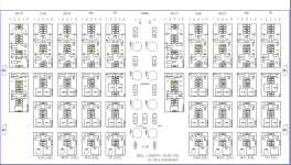
Speaking of which I am ready to begin testing! Here is what the board looks like now. As you can see, because my speakers are 3-way, I have not fully populated the SUB section, SUB GAIN section or HI PASS area of the WOOF section.

During the wait I did some more work with the online calculator and settled on the values for Rs and Cs in those parts of the board that should get me the 600Hz and 4kHz factory-standard crossover frequencies for my speakers.
Values for 600Hz High Pass (to populate "MID HI PASS" Section of Board)
C1= 10nF R1= 30k C2= 10nF R2= 30k
Values for 600Hz Low Pass (to populate "WOOF LO PASS" Section of Board)
C5= 22nF R5= 10k C6= 33nF R6= 10k
Values for 4kHz High Pass (to populate "FR HI PASS" Section of the Board)
C1= 47nF R1= 150 Ohm C2= 1000nF R2= 470 Ohm
Values for 4kHz Lo Pass (to populate "MID LO PASS" Section of the Board)
C5= 330nF R5= 30k C6= 10nF R6= 7.5k
Although confident I have the right sections of the the board, I'm uncertain which of the two resistor or capacitor slots in MID HI PASS or FR HI PASS correspond to R1 vs R2 or C1 vs C2. Likewise which of two resistor or capacitor slots in WOOF LO PASS or MID LO PASS correspond to R5 vs R6 or C5 vs C6. I decided to assign the lower number to the top resistor slot or the left capacitor slot.
If anyone knows the answer please let me know. It might save me a LOT of grief in troubleshooting. 😱
Speaking of which I am ready to begin testing! Here is what the board looks like now. As you can see, because my speakers are 3-way, I have not fully populated the SUB section, SUB GAIN section or HI PASS area of the WOOF section.
Last edited:
It's not the HOW, it's the WHO that matched them. Nelson Pass supplies all the matched JFET's with resistors, all of the resistors for the JFET's are the same. You can install the JFET's and resistors since they are all the same in any position on the PCB you want.to respond to a question about how the J-FETS and resistors were matched.
That will leave only the R1,R2,C1, C2 answer, there you might need to use an ohmmeter to trace the PCB to the schematic. Do one at a time and double / triple check your results. Don't assume the positions are the same for each section of the PCB, trace each sections R1,R2,C1 &C2.
Don't forget to finish the SUB section, the PCB fully completed now is better than finding out someday you want to add a SUB and can't find the parts to complete.
How can I find Q1 (J113) with suitable Vp ?
I bought over 300pcs of J113 but my input buffer still has dc offset 0.7Vdc but when I changed to 2SK170 gr its dc offset go down to 0.01Vdc. Then I thought my J113 aren't match to this point.
I bought over 300pcs of J113 but my input buffer still has dc offset 0.7Vdc but when I changed to 2SK170 gr its dc offset go down to 0.01Vdc. Then I thought my J113 aren't match to this point.
- Home
- Amplifiers
- Pass Labs
- Can you help me to modify crossover points on a Balanced LXMini Crossover?