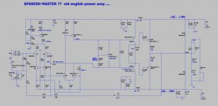
"Hello friends, I need your help. Three years ago, I made some changes to a circuit designed by a Spanish master who has since passed away. The original schematic was designed as a complementary circuit with a pair of 5200 transistors, and it was a Class AB amplifier circuit.
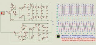
I have made two different configurations from this schematic. One is a 300W RMS amplifier with 3 pairs of complementary PNP and NPN transistors, and it is driven by a single differential pair with torque and differential terminology which I am not familiar with. The power supply is +-65V.
The other configuration is a 100W RMS amplifier with a pair of complementary PNP and NPN transistors, and it is also driven by a double differential pair."

"I tried to simulate the circuit as much as I could in ARES, and I have uploaded the results as both a PDF and ARES file. The results are a bit confusing, so I wanted to get your opinion and see if there are any errors or mistakes. Can you take a look? Both the PDF and ARES files are available."
"I apologize, I don't speak English so I used a translator. I am wondering if there are any mistakes or incorrect parts in two circuits I designed and simulated in Ares, and I have uploaded the results as both a PDF and Ares file. Could you take a look and give me your thoughts?"
I have made two different configurations from this schematic. One is a 300W RMS amplifier with 3 pairs of complementary PNP and NPN transistors, and it is driven by a single differential pair with torque and differential terminology which I am not familiar with. The power supply is +-65V.
The other configuration is a 100W RMS amplifier with a pair of complementary PNP and NPN transistors, and it is also driven by a double differential pair."
"I tried to simulate the circuit as much as I could in ARES, and I have uploaded the results as both a PDF and ARES file. The results are a bit confusing, so I wanted to get your opinion and see if there are any errors or mistakes. Can you take a look? Both the PDF and ARES files are available."
"I apologize, I don't speak English so I used a translator. I am wondering if there are any mistakes or incorrect parts in two circuits I designed and simulated in Ares, and I have uploaded the results as both a PDF and Ares file. Could you take a look and give me your thoughts?"
Attachments
The TIP41/42 is definitely not suitable (40v rating). Even a TIP41C/42C are marginal for -/+50 volt rail. The fixed bias scheme isn't great either however there is nothing obviously wrong with the topology that would stop it working, in fact its almost a bjt output version of the old Hitachi Lateral FET amp from the late 70's.
D1 and D5 Zener 24v
I think you want me to cancel R45 and R46 Also Q25 and Q26
Do you want me to connect R35 and R36 directly in Q23 and Q24, is it true?
Normally in 100w amp scheme
Q15 type42 Q16 and Q19 Type41 were used and the supply voltage was supplied with -/+ 50v
But since I converted the Amp from N-channel to NPN AND PNP, I used Q15i Tip42C and replaced Q16 with D718 Q19u B688
My Purpose Was To Evaluate The Transistors I Have
I'm going to use these amps with 4ohm Hapörler.
What I'm wondering now
1- 300w amp is fed with +/-65v
2- 100w amp is powered by +/-50v
Can I Operate Both These Amps With The Same Voltage Without Loss of Power For example, what changes should I make with +/-55v?
Finally I Updated the File I Made Zip Format
Attachments
R45, R46, Q25 and Q26 are cascodes for the input differentials - that's ok.
I assume a "Hapörler" is a 'haut-parleur' (french), aka a loudspeaker.
"...What I'm wondering now..."
That involves a lot of calculations and review of possiblilities.
You can hire me to do it, but I'm expensive (250ph).
Made a screenshot of the designs for ease of access.
I assume a "Hapörler" is a 'haut-parleur' (french), aka a loudspeaker.
"...What I'm wondering now..."
That involves a lot of calculations and review of possiblilities.
You can hire me to do it, but I'm expensive (250ph).
Made a screenshot of the designs for ease of access.
Attachments
schematic posted in op / post #1
Can be greatly improved
Overall some components can be removed.
Also some additional improvements need to be added.
It is quasi complementary output stage.
If your interest is building quasi amplifier, changes need to be made.
otherwise easily converted to Complementary pair
As mentioned Texas Instrument Power or TIP transistors
very poor outdated general purpose transistors
not suitable for audio amplifier use.
Or voltages presented
5uH of output inductor is overkill value and ruin
high frequency performance.
Plus numerous compensation capacitors used
are poor values
so they don't help in this section, should I open a topic in another section?
If so, in which section should I open the topic?
If so, in which section should I open the topic?
I simply meant that Citizen124032 was not making a serious comment with you about charging a fee.

@Malicarpar: I'm willing to help (for free) to a certain limit. But as WhiteDragon in #7 already notes, there are a lot of issues to address in your circuits. It will take a considerable time to have it all discussed and explained. This site and its members are not a humanoid form of chatGPT where can throw in some ideas and questions and expect rock solid answers and solutions as a result. Make drawings in accordance to standards, study electronic amplifier circuits, compare, read, try, build, test, burn, give up, continue. The internet is for free, and loaded with commercial content too.
I would like to start by apologizing to you, I am not a graduate or a graduate of this business.
I am a novice in this hobby that I do in my spare time, I came to these days with trial and error, the diagram in #1 above is the original diagram and I compared a few similar diagrams and made a new drawing, I made a drawing based entirely on assumptions.
forgive me for being ignorant and inexperienced
forgive me for not speaking english
I try to produce as much as I can, even though I am ignorant and inexperienced, for this reason the opinions and ideas of you masters are very important to me.
With your help, I have achieved success in what I have done so far.
English is not my language either, and you don't have to apologise.
Start browsing this forum for amplifier circuits and the comments. Visit the various links provided. Visit your local library and see if books about electronics are available. Read, read, study. Start with simple circuits to build: a tone generator, a power supply, a (555) timer circuit. Lot's of fun. Progress towards amplifiers at your own pace.
Remember Murphy's law: "Amplifiers turn into oscillators. oscilators won't oscillate."
When you say many problems, can you give a few examples?@Malicarpar: I'm willing to help (for free) to a certain limit. But as WhiteDragon in #7 already notes, there are a lot of issues to address in your circuits. It will take a considerable time to have it all discussed and explained.
about what is causing the problem
For example: C-x Value Low R-x Value Excess Q-x Connection Seems Wrong
Current source (R49, 33k) from a regulated supply is very unusual, maybe not neccessary. Curious and unique though.
Cascode with R66-R67 can inject ripple from the negative rail - a current source from the rail will prevent that.
There is no HF compensation in the first stage - it might oscillate.
C18, C19 are miller cap's for Q30, Q33, but is this the right way / the proper values? The BJT's are on the edge.
Q30 is the counter for Q1, but very different. Is Q1 fit for the supply voltage? See remarks #3.
Bias setting with D11, D12 and R60 is very simple, but not very reliable, and with temperature drifting Q29-Q34 will drift too.
The VAS must run on 42mA at least to hop over class B setting, which is very high.
I doubt the values of C17 and C20 - calculations or proof needed.
Add a resistor of >100k on the connector side of C22 to prevent pops when connecting a source.
Zobel network.
HF compensation over R68.
Add values of node voltages and collector currents from the simulations to the circuit diagram for better understanding.
Run a dc analysis injected on the base of Q36 and see if things remain stable.
Run a ac analysis from sub frequency up to 10MHz, a Bode plot (dB and phase) and absolute voltages and currents if all values fits the specs of the components.
Run an ac open loop gain analysis (R68 not connected to the output but to ground), with reduced level (obvious) and observe the behaviour of the amp, especially the higher frequencies. A Bode plot shows hidden zero's and most important hidden poles!
Run if possible a transient analysis.
Run a dc supply start-up & shut-down analysis - is the amp stable during these transits or is destruction looming
Do a power supply analysis - what is needed (voltage, current, caps, bleeders, bridge current peaks, transformer performance, mains filtering).
Do a PSRR analysis - what amount of supply ripple will be injected where and how much and how to reduce it.
Make a plan for a build, wiring, component placing, grounding, safety, ventilation & heat sinks, operability, transportablity, EMC behaviour.
Just to address a few.
Hopefully it sounds a bit decent. But that's only known after all the effort has been done.
There was another circuit involved too, not?
Same issues.
But I wish you well, good luck with the design and above all: a lot of fun and pleasure!
Hello Ustam, the closest to the component values, the results of the simulation and tests I have made with the components found in Ares, I tried to test what you say as far as I can understand.


Nice plots! Ok with the voltages shown.
I have no experience with ARES (do you have a link where to refer to / download?), but most is understandable.
First plot Gain/Phase: curious gain lift below 100Hz, falling above 1kHz onwards, phase corresponding. But the scaling is extreme!
Second plot: what do we see here? A sine and another clipped sine wave?
Third plot: a more realistic Bode plot, slighty peaking at 30kHz, could hint for oscilation in real life. Phase starts to divert from 10kHz onwards - keep in mind that our ears are sensitive for phase differences above 2kHz as this carries directional information (below 2k it is amplitude driven; this is defined by the distance / wavelength between our ears). Keep the phase flat well above 20kHz, that's a challange and makes all the difference! This a general difficulty for all high gain closed loop amplifiers and it takes painstaking effort to get things at premium quality. But there are well forged designs, many can be found on DIYaudio! This phase issue has another side: if three devices are connected in series (audio source, amplifier, loudspeaker) and all have a 'HiFi' specification of an overall (closed loop) bandwith of 20kHz @ -3db (equals -45º), the result is -9dB (-135º) overal system performace at 20kHz. In summary, whatever the topology, it's (with those high gain amps) this very high frequency and stablility beast to get in control!
Fourth plot is somewhat puzzling, 'distortion analysis'. How to read this? It looks reasonable below 2kHz, but above it's a roller coaster.
Can you make a Bode plot (amplitude/phase) in the same scale as the third plot, but the amp running in open loop according to #16 ("R68 to ground")? Input signal 40 dB lower then applied in plot 3! It will show what the amplifier is actually is doing inside ('while amplificating').
You need to use LTspice. Your amp is actually "olde English" , the Spanish master copied it.
The LT version of this amp is posted. Actually , very clean for this simple amp. .01% at 20k. NICE !
The 2 files (.asc + the cordell models) go in the same folder. Sim will run good.
This is a good topology to build ..... Q6/7/8 can be mje340/350... any ??? on my extra additions or component choices ,
feel free to ask.
Go to https://www.analog.com/en/design-center/design-tools-and-calculators/ltspice-simulator.html best stuff !!
"Well forged designs" he he he !! Like Badgers and Wolverines ?
Attachments

- Home
- Amplifiers
- Solid State
- Can Transistor Amplifier Experts Help?