+1 100% agree.
Those transformers are listed for sale online in Japan for $5-$7 - less if you order 100!
1K primary (dcr 57Ω) to 2K secondary center tapped (dcr 160Ω) Ratio 0.7:1
Maybe you can find a reasonable sub , or maybe the US Hashimoto distributor can get a pair thrown onto his next shipment for not too much?
That's what I am looking for - a reasonable substitute. I looked at the offerings from Edcor as suggested above, but I don't know enough about what I am looking at to know what to order. I actually need a very specific recommendation, a 'go buy this' link, if someone more knowledgeable than I would be willing to assist me with that.
Exciting news - I found a couple companies that are based in Japan and which specialize in acting as a buying agent for items that can't be obtained in the US. They buy for you, charge a commission, postage, handling, etc, and then forward to you. This will necessarily treble the cost of the transformers, but if I cannot find a domestic substitute, that's probably what I'll end up doing.
Google translation from the horse's mouth: "600Ω primary, connect the secondary to 10kΩ tap, the secondary was made with 100kΩ resistance two because there is no middle point tap. Gain becomes higher is a good feeling."
I take this to mean that Edcor's WSM series ordered with 600R primary and 10K secondary (WSM600/10K) would be just peachy. The price is $10.44 each. Since it has a center tapped secondary, the original author's 100K resistors wouldn't be necessary. One often finds that some secondary loading is necessary to damp transformer resonance, however. Edcor's chart does show a rising response above 20KHz, but it ends before plotting the peak. This is something that's easy to determine experimentally if you have basic audio test gear.
I take this to mean that Edcor's WSM series ordered with 600R primary and 10K secondary (WSM600/10K) would be just peachy. The price is $10.44 each. Since it has a center tapped secondary, the original author's 100K resistors wouldn't be necessary. One often finds that some secondary loading is necessary to damp transformer resonance, however. Edcor's chart does show a rising response above 20KHz, but it ends before plotting the peak. This is something that's easy to determine experimentally if you have basic audio test gear.
I have a scope, but only know basics of how to use it. Multimeter of course.
Scopes are easy, do you have the manual?
You'll also need an audio signal generator, or else a PC with software to make waveforms.
Google translation from the horse's mouth: "600Ω primary, connect the secondary to 10kΩ tap, the secondary was made with 100kΩ resistance two because there is no middle point tap. Gain becomes higher is a good feeling."
I take this to mean that Edcor's WSM series ordered with 600R primary and 10K secondary (WSM600/10K) would be just peachy. The price is $10.44 each. Since it has a center tapped secondary, the original author's 100K resistors wouldn't be necessary. One often finds that some secondary loading is necessary to damp transformer resonance, however. Edcor's chart does show a rising response above 20KHz, but it ends before plotting the peak. This is something that's easy to determine experimentally if you have basic audio test gear.
Its asking a lot from such cheap transformers to give a 4:1 voltage step up and drive a valve into positive grid territory. Unfortunately I would predict a fairly disappointing result.
Shoog
Its asking a lot from such cheap transformers to give a 4:1 voltage step up and drive a valve into positive grid territory. Unfortunately I would predict a fairly disappointing result.
Shoog
Yes, DC grid current flowing in the secondary (that also has 4x more turns) is likely to be the first limiting factor even if one uses a proper OP-amp to drive the low input impedance.
These tiny signal transformers don't have a proper gap. They can only rely on a slight mismatching of E and I lamitations which can only guarantee imuunity to very small DC currents. In theory output power could be even more than 1W, in practice it will be a small fraction and limited by input transformer saturation which will produce a really nasty sound.
280-290V supply and 470R common cathode resistor for the 12AU7 to stay away from grid current is the simple solution....
Why not drive the IT iron with a cathode follower that is cap coupled to the iron?
Also it would likely not be terribly difficult to use the larger wattage (also inexpensive) version of the
Edcor iron, take out the lams and gap it... the current from the grid on a single 12AU7 is really going to
be kind of really kind of small? (the thinking behind the larger version is to perhaps maintain enough L
at lower freqs...)
_-_-
Last edited:
I think 45's suggestion is entirely more sensible. Keeping the valve away from any grid current will make it more versatile since just about any preamp will be able to drive it well. The higher voltage requirement is not an issue since a very cheap power supply can be built using DC-DC boosters (especially at this current).Why not drive the IT iron with a cathode follower that is cap coupled to the iron?
Also it would likely not be terribly difficult to use the larger wattage (also inexpensive) version of the
Edcor iron, take out the lams and gap it... the current from the grid on a single 12AU7 is really going to
be kind of really kind of small? (the thinking behind the larger version is to perhaps maintain enough L
at lower freqs...)
_-_-
Something to think about is the fact that for minimal extra complexity a negative grid bias for the 12AU7 can be supplied to the input transformers center tap.
The pursuit of simplicity at the expense of basic performance is wrong in my opinion.
Shoog
I just realized there's another problem here -- grid current adds to cathode current and will cause the CCS to reduce anode voltage under drive. I still think Wig could have a lot of fun with this project and I trust he will persist.
I couldn't help but steal some of that fun vicariously, so I sketched up a class AB2 design concept of my own. I reckon this version could yield as much as 2.5W with a 10KCT OPT, B+ at 160V, and grid bias around -2V for idle current of 15~16mA on each side. The PSU transformer(s) needs a 120V winding and a 12.6V winding to yield all operating voltages. Grid drive has to reach +12V on peaks, which implies 2.4Vrms input to the Edcor WSM600/10K. Many preamps can do that. The WSM600/15K would help matters a bit.
Ack! I messed up the attachment somehow... View attachment 552863
Last edited:
I just realized there's another problem here -- grid current adds to cathode current and will cause the CCS to reduce anode voltage under drive. I still think Wig could have a lot of fun with this project and I trust he will persist.
I couldn't help but steal some of that fun vicariously, so I sketched up a class AB2 design concept of my own. I reckon this version could yield as much as 2.5W with a 10KCT OPT, B+ at 160V, and grid bias around -2V for idle current of 15~16mA on each side. The PSU transformer(s) needs a 120V winding and a 12.6V winding to yield all operating voltages. Grid drive has to reach +12V on peaks, which implies 2.4Vrms input to the Edcor WSM600/10K. Many preamps can do that. The WSM600/15K would help matters a bit.
Ack! I messed up the attachment somehow... View attachment 552863
Thanks, I do plan to proceed. I can always modify the circuit as needed. Unfortunately I can't see your attachment for some reason.
Why not drive the IT iron with a cathode follower that is cap coupled to the iron?
Also it would likely not be terribly difficult to use the larger wattage (also inexpensive) version of the
Edcor iron, take out the lams and gap it... the current from the grid on a single 12AU7 is really going to
be kind of really kind of small? (the thinking behind the larger version is to perhaps maintain enough L
at lower freqs...)
_-_-
Why don't you bias each triode of the 12AU7 with a DC coupled source follower and forget about re-gapping transformers without info about the windings, CCS, OP-amp etc.?
It only costs a couple of FETs, few resistors & caps and tap on the secondary HV winding. From the tap you make a voltage doubler and then filter the dual supply for the source follower....
There are many things one can do but it seems to me that the OP is not experienced because he is asking for an alternative design. So a simple circuit that more or less works is the best start IMHO.
290V supply and 470R common cathode resistor + input transformer is one. Alternative solution: same output stage with self-bias resistor and the ECC88 as voltage amp + concertina and he doesn't need any preamplifier.
They are really the simple, class A and should get about 1W. Not bad as a start.
If one starts with something more complicated that is not able to manage and it doesn't work (doesn't sound good) I think he will lose interest...
Okay, let's try this again:
If you want the OP to build this circuit then you have to tell him how to make supply as well.😀
I think 45's suggestion is entirely more sensible. Keeping the valve away from any grid current will make it more versatile since just about any preamp will be able to drive it well. The higher voltage requirement is not an issue since a very cheap power supply can be built using DC-DC boosters (especially at this current).
Something to think about is the fact that for minimal extra complexity a negative grid bias for the 12AU7 can be supplied to the input transformers center tap.
The pursuit of simplicity at the expense of basic performance is wrong in my opinion.
Shoog
Except that not running it in A2 rather obviates the whole effort of having an IT transformer, and limits the max power even further...
Agree on the bias thing, fwiw... it's certainly a way to go.
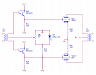
I'm afraid that's a bit beyond me, but I understand parts of it, I think. Are you saying that based on the schematic shown, the amplifier cannot function?
I suspect there is an error in the schematic. There should be no connection from the cathodes to the transformer. The centre tap of the transformer should go to 0V. Apart from the use of diodes, this is a very common topology in old professional audio designs from the 1940s.
Cheers
Ian
I suspect it is a design flaw rather than an error i.e. it is a deliberate error. To get much output from a P-P 12AU7 you need to run it in Class A2 with little or no grid bias.
To get much output from a P-P 12AU7 you need to run it in Class A2 with little or no grid bias.
That's exactly the topology of original design linked in post #1. The center tap is connected to the cathode and not ground according to its designer.
Go for it!Thanks, I do plan to proceed. I can always modify the circuit as needed.
I started in electronics when I was about eight years old, at first carefully following simple schematics. Not that long after, I substituted my first part - most probably a resistor value I didn't happen to have handy. To my surprise, the universe didn't come to an end, and the circuit worked, too! 😀
After that, still a child, I was bolder at experimenting with different parts values and so on. Most of the time, the circuit worked. If not, I moved on. As I grew older, I found out that the most valuable step was to find out why the circuit wasn't working before I moved on. We can learn a lot from designs that don't work properly!
My point being, just to have a little fun playing with the circuit, all you need is any audio transformer with one side centre-tapped, and roughly a 1:1 winding ratio. Don't worry if it's too big, too small, not exactly 0.7:1, or any of those details. For your purposes, it doesn't matter a pestiferous rodent's behind!
Here is a $3 transformer from All Electronics (in Southern California, USA) that will do the job. Both primary and secondary are centre-tapped. Winding ratio is 1:1. It is tiny, cheap, and won't handle much power, all of which are perfectly in keeping with the philosophy of this circuit:
LINE MATCHING / COUPLING TRANSFORMER | All Electronics Corp.
Similar 600 ohm: 600 ohm, centre-tapped audio signal transformers can still be found at multiple suppliers, so if you have a more local electronics supplier, see if they have anything similar.
-Gnobuddy
- Status
- Not open for further replies.
- Home
- Amplifiers
- Tubes / Valves
- Can someone help me understand this topology?