If you look at the curves on the datasheet, you will see that zero grid bias is about right for designed cathode current in this setup. So it should work just fine, but understand that you're working in class A2 here. The grids go positive under drive so it's important to provide a very low driving impedance to keep distortion under control. This output stage might be an ideal candidate for direct op-amp drive, if you're interested in that sort of thing.
yes
The problem is that there isn't enough voltage for the current source.The tube needs all the supply to get to the imposed current at Vg=0V.
Result is the source doesn't funtion properly giving crossover distortion.
Mona
Result is the source doesn't funtion properly giving crossover distortion.
Mona
The problem is that there isn't enough voltage for the current source.The tube needs all the supply
to get to the imposed current at Vg=0V. Result is the source doesn't funtion properly giving crossover distortion.
Then the current source can be connected to a negative voltage supply. That's part of the design process.
Or like this 😀Then the current source can be connected to a negative voltage supply. That's part of the design process.
Mona
Attachments
Or like this 😀
Mona
Sure, a current source that only requires a low voltage drop to function is one option.
It's a daft circuit. Some people in some places seem to like daft circuits. It will 'work' in the sense that if you put an input in you will get some output out, but don't expect any degree of fidelity.
The fact that it uses no resistors or capacitors is not a plus point, as it uses transformers and valves - both of which are far less ideal in behaviour than resistors and capacitors. The linked page shows versions of the design with direct mains connections; that should be a warning that this is not a serious audio website but just someone playing with idiosyncratic circuits.
The fact that it uses no resistors or capacitors is not a plus point, as it uses transformers and valves - both of which are far less ideal in behaviour than resistors and capacitors. The linked page shows versions of the design with direct mains connections; that should be a warning that this is not a serious audio website but just someone playing with idiosyncratic circuits.
Transformers are blameless. Capacitors are just wrong.The fact that it uses no resistors or capacitors is not a plus point, as it uses transformers and valves - both of which are far less ideal in behaviour than resistors and capacitors.

Last edited:
Capacitors in combination with non-linear currents add more harm than transformers, when improperly used. But capacitors are much more linear than transformers.
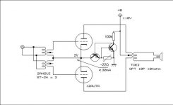
In this case it is supposed to drive a speaker. So it must have an output transformer. The Toei 10P is tiny (just a bit smaller than a 6 cm cube for 0.75Kg weight) output transformer. It's 10K:8R (or 4R).
I think properly done it can be quite linear and provide approx 0.7-1 W class A(2) power with very low distortion.
I think properly done it can be quite linear and provide approx 0.7-1 W class A(2) power with very low distortion.
The datasheet of the Toei 10P suggests to use tubes with Rp not higher than 2k, and primary impedance is 8k not 10k....
With 12AU7 (Rp ~7k) this circuit will not provide HiFi I guess; 5687, 6H30, ECC99 and likes would perform better.
It seems better to put the output transformer in the cathode circuit as there is already very little if any voltage gain.
With proper anode voltage the DC resistance of the primary can be used for better biasing of the tubes.
Hi,
The ST24 is a 1K:2K transformer, (ratio 0.7:1) but its
main purpose it to act as a phase splitter as I see it.
I can't see why standard 600R types would not work.
(In fact I think loads of small transformers would work.)
Can someone recommend a particular transformer that would work in this position as an input transformer to perform the phase-splitting duties? I'm afraid input transformers are way outside my experience. I google for them and I have no idea what I'm looking at.
For reference, the Japanese vendors of the ST-24 that I can find seem to be selling the ST-24 for about $4.25 USD each, so I'm looking for something in that range. When I google for input transformers, I'm seeing anything from $100 to $700, and that just isn't in the cards for me.
Thanks!
That circuit has an unusual way of adjusting bias, as has already been pointed out. Instead of adjusting grid-cathode voltage to get the desired anode current, it adjusts the anode-cathode voltage. This wastes more power, but I suppose this doesn't matter too much in a novelty circuit.
primary impedance is 8k not 10k....
10P is referred to the power rating. There are 5K, 8k and 10K versions.
I don't think so. To get 0.7-1W output you only need approx. 15-20V grid-to-grid. The problem is that it's driven into positive grid....there is already very little if any voltage gain.
Last edited:
but I suppose this doesn't matter too much in a novelty circuit.
I agreee this time....
Can someone recommend a particular transformer that would work in this position as an input transformer to perform the phase-splitting duties? I'm afraid input transformers are way outside my experience. I google for them and I have no idea what I'm looking at.
For reference, the Japanese vendors of the ST-24 that I can find seem to be selling the ST-24 for about $4.25 USD each, so I'm looking for something in that range. When I google for input transformers, I'm seeing anything from $100 to $700, and that just isn't in the cards for me.
Thanks!
If you really want to use that power stage I would recommend using a DC coupled source follower that takes care of the grid current and power requirements and also biases the 12AU7. So cathodes would be grounded.
Then I would add a simple SE voltage amp + concertina or a LTP. If you don't want to use additional tubes you could try with JFets as the required voltage swing is small.
Using a step-up transformer makes it even more difficult for the source that should drive this power amp. Actually I would not even call it a power amp but rather a booster!
I appreciate the advice, although I'm afraid that due to my ignorance, I can't really make use of it. I understand it lightly, on the surface. I'm not discounting your expertise in the least, and I appreciate it. Just not able to implement it at my level of understanding.
But supposing I just wanted to buy an inexpensive equivalent of the specified Sansui ST-24, can someone suggest a specific replacement available in the US?
If you want to make it easier then remove again those diodes and use simple self-bias resistor. This time anode supply voltage would be some 260-280V (for effective 250-270V anode voltage) and current 10 mA per tube. In this case the input transformer would not be limiting as in the other case but still you need to see its reactive load presented at higher frequency. Someone was suggenting specialized OP-amps to drive 600R-1K input transformers. This is not a bad idea at all. You can pick a good one and start copying suggested circuit in datasheet. You need a preamp anyway even with that input transformer. Increasing the step-up makes things worse for the source that has to drive it because the capacitive load is multiplied by n^2 (n being the turns ratio).
The original idea started with that low anode voltage to connect directly to the line (bad idea, IMHO). Just use a proper supply transformer.
Last edited:
I don't think so. To get 0.7-1W output you only need approx. 15-20V grid-to-grid. The problem is that it's driven into positive grid.
Input transformer 1 : 1.4
Voltage gain of the tubes some 24?
Step down ratio of the output transformer 50 : 1 (10k:4R)?
Where do you get your voltage gain?
I did not mean power, but I trust you know the difference 😉
Last edited by a moderator:
If you want to make it easier then remove again those diodes and use simple self-bias resistor. This time anode supply voltage would be some 260-280V (for effective 250-270V anode voltage) and current 10 mA per tube. In this case the input transformer would not be limiting as in the other case but still you need to see reactive its reactive load presented at higher frequency. Someone was suggenting specialized OP-amps to drive 600R-1K input transformers. This is not a bad idea at all. You can pick a good one and start copying suggested circuit in datasheet. You need a preamp anyway even with that input trnasformer. Increasing the setp-up makes things worse for the source that has to drive it because the capacitive load is multiplied by n^2 (n being the turns ratio).
The original idea started with that low anode voltage to connect directly to the line (bad idea, IMHO). Just use a proper supply transformer.
OK, I follow most of that, but I am afraid I have no experience with input transformers and don't know how to 'pick a good one'. I'm actually hoping someone can give me a link or a brand name / model number that I can purchase without breaking the bank. Thanks!
- Status
- Not open for further replies.
- Home
- Amplifiers
- Tubes / Valves
- Can someone help me understand this topology?