hey guys, im trying to design a crossover for a 6" SB17MFC35-4 and a SB29RDNC-C000-4
I have been doing lots of research on crossover but i just can decide on a frequency and type of crossover. from what iv worked out a 2000hz 4th order butterworth would be the best, but someone else is telling me a 4th order butterworth at 4000hz would be better, but i just can comprehend why the best i could work out is that its because our ears are less sensitive above 3000hz.
cheers guys.
Hi Mauds,
i would aim for 2k ...2,3k effective acoustical crossover frequency.
But when going passive 4th order is way too high IMO even for practical reasons.
At the lower XO frequencies you will have a more uniform dispersion, without the woofer beaming too much, as you have to expect it with a higher XO like 4k (way too high).
Vibrational modes will also be less a problem, with the woofer crossed lower.
About 2 octaves above Fs of the tweeter (600Hz) should be still "sane" when using a 2nd order Filter.
That tweeter will need at least some electromagetic damping as Qms is quite high:
If you use an L-Pad, a rather low resistor in parallel (e.g. 6Ohms) can provide at least some EMK-damping even in the region below the highpass filter's cutoff.
Alternatively you can compensate the resonant peak using an LCR series resonator in parallel to the tweeter.
Compensation of the impedance to be almost flat for both drivers in the "wider crossover region" will improve your filter.
Important:
You should optimize baffle shape and mounting positions of both drivers using e.g. "Edge" from Tolvan Data or any other well behaved "baffle diffraction software".
Edit: A higher crossover frequency is only recommended, if want to use that speaker (2-Way?) to be driven at higher levels: Then a higher crossover frequency would reduce voice coil travel and temperature for the tweeter.
But if you aim for low coloration in a 2-way, which seems the case when looking at your driver choices, i would go the "low fc" way as mentioned above.
Cheers
Last edited:
... one can do that, surely.
But unecessary IMO, because this is kind of "standard configuration" stuff.
Lower fc will yield the better speaker, it is as simple as that.
And: One has to design for a certain fc from the beginning, which also affects the baffle design and positions of the drivers.
So "designing" is (by far...) better than "trying" at that point IMO.
Cheers
Hi tuantran,
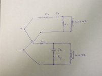
as a simple starting point maybe ...
But this crossover will provide
- too less electrical damping for the tweeter
- will be influenced in slope too much by the impedance peak of the tweeter
- has too less steepness in the cutoff region for the woofer
Target should be 12dB/octave acoustical rolloff for both drivers IMO
Last edited:
Both of those drivers are are fairly easy to work with.
Chart 1: For the SB17MFC35-4, it looks like the -3dB point at 45* off-axis will be somewhere at about 2500Hz, so that should be your upper limit for the woofer in terms of directivity.
Chart 2: Looking at the 8ohm version which should have pretty similar performance, harmonic distortion of all kinds remains low all the way up to 3000Hz, so that's fine too.
Chart 3: Cone resonances also start to increase above 3000Hz, so overall I would stay below about 2500Hz or so for the woofer.
Chart 4: In terms of the tweeter, 3rd order harmonic distortion starts to increase below about 2500Hz although at 2000Hz, it's still below -70dB which is still fantastic. So given the low Fs, I'd look at crossing somewhere around 2000-2500Hz.
Personally, I go for 4th order LR acoustic slopes, which you may be able to achieve with 2nd order electrical but you may need to go to 3rd order electrical on one or both to do that and to keep phase in good alignment. I've had good success in simulations with that tweeter with values in the neighborhood of 8-10uF/.2mH/15-25uF depending on baffle size and driver placement.
What are you using to design the xo btw?
Attachments

Hi Jreave,
we don't seem to disagree on this ... LR 4 with -6dB crossover point
seems fine. Also there is agreement concerning the crossover frequency.
Nevertheless this is my "minimum Option" in contrast to the pic posted above (post#5) ...
http://www.sbacoustics.com/files/5513/4918/9993/6in-SB17MFC35-4-chart.gif
http://www.sbacoustics.com/index.php/products/tweeters/sb29rdnc-c000-4/
Attachments
Last edited:
In all honesty, you really can't guess about the crossover. It begins as a measurement issue. Much later you can season to taste.
The first order of business is to get/measure the 1) on axis frequency response of the components 2) phase response, 3) non-linearities (2nd and 3rd harmonic distortion are good candidates) and 4) dispersion at the ballpark frequency of the crossover. Folks will weight these factors differently, but this is a good start.
The first order of business is to get/measure the 1) on axis frequency response of the components 2) phase response, 3) non-linearities (2nd and 3rd harmonic distortion are good candidates) and 4) dispersion at the ballpark frequency of the crossover. Folks will weight these factors differently, but this is a good start.
Last edited:
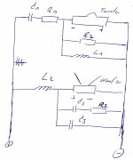
... when guessing i would have written values beside the elements 🙂.
I am pretty sure, that this configuration will work as such and that there should not be "less elements".
Furthermore i agree to Jeff Bagby and jReave, that an electrical 18dB configuraton at the tweeter might be better do fit phase and group delay on a flat baffle.
But you are right:
We won't get around some measurements when matching this XO to the real drivers.
But @Maud's first question was about "raw design" i.e. crossover frequency and topology of the circuit.
Given a spare parts box with enough elements and using my teeth to strip the wires, i can match that circuit also "by ear" in case of emergency .... it is rather well behaved.
Last edited:
I ment by measurement & by ear. Measure the drivers, listen to all the x-overs that seem to work for the drivers at different x-over points in the simulation? Am i that old fashioned? In the end you will end up listening to it anyways...No offence ment but measurement + simulation = the new textbook alignment? -edit- what Bagby says in the pdf- but without the LR4 is best-edit
Am I old fashioned?... normally choose the crossover point as above for ballpark and then use -6dB as actually measured @ 60° offaxis on a mockup baffle that is a copy of the real thing. The last 6.5" midwoofer I tested called for 2.2k based on the manufactures pdf, but when measured this dropped to 2.1k. On the plus side the 4-5k peak normally associated was better suppressed than pdf would suggest, which wasnt bad to begin with.
Linearray> why would you put a zobel on a woofer1) that has such low Le, 2) when modern modeling software renders zobels (for your purpose) nearly always unnecessary?
Hi,
what is "modern modelling" software ?
Is "modern" a software which chooses the circuits topology for you ?
When listening on axis you cannot afford the steepness of the crossover
being any lower than required.
This is where the RC member is for.
One may tune it differently than needed for "perfect flatness of impedance" depending on the woofer.
But it definetely helps reaching the recomended steepness, which is also
important for frequnecies say 1 .. 2 octaves above crossover, when listening on axis.
2-ways missing the full steepness of crossover at the woofer often sound too "dirty" in lower highs: Beaming and partial resonances of the woofer contribute to that. In a high quality speaker, one cannot tolerate that.
No matter what someone's "modern software" says.
I agree with you, that there are woofers which may call for a zobel more urgently. On the other hand, this one has a "nice rise" on axis, and impedance is rising above fc, even if "creepingly".
There are also more elaborated impedance equalizing circuits than just a zobel, but i did not want the crossover to get overly complicated:
Mauds has drawn an electrical 4th order already ...
I want to keep it as simple as possible, but not simpler and in a "well tempered manner" for tuning and modification. This is also what the parallel resistor for the tweeter is good for. It is somewhat "simple", but it works well ...
There are all sorts of circuits and layouts that can be used for shaping response, but *I'm assuming* you intend that zobel to work in the traditional way, merely to flatten the woofer impedance? Prior to modern modeling software, this helped those idealized calculators accomplish a response that wasn't terrrible, and more predictable. But that has been completely replaced by modern methods as far as i can see.
Do you think I cannot form an equivalent frequency response without using a zobel? Unless you have a specific response shaping issue identified that will require this RC shunt, I'm not sure why you would include it in a prototypical crossover?
Do you think I cannot form an equivalent frequency response without using a zobel? Unless you have a specific response shaping issue identified that will require this RC shunt, I'm not sure why you would include it in a prototypical crossover?
@augerpro:
Omitt it if you like.
When it comes to implement such a 2-Way speaker, i am very shure to introduce that RC-element afterwards.
It does not have to be "standard valued", but you cannot keep 12dB/Octave slope without it. On axis this means, that the "dirt" of the woofer still radiated fairly above crossover contributes a few dBs more than it should: That is reason enough to use that option IMO.
But we don't have to worry about that: I am fine with omitting it in a first Prototype (in this particular case ...) 😉
Of course you can't: Especially in our case, where we will have fc rather low and want to control the rolloff even far above fc in a way to be steep enough.
If you strictly avoid listening to that 2-Way directly on Axis, that might be less important.
But then we have a "speaker of resricted use" IMO.
Omitt it if you like.
When it comes to implement such a 2-Way speaker, i am very shure to introduce that RC-element afterwards.
It does not have to be "standard valued", but you cannot keep 12dB/Octave slope without it. On axis this means, that the "dirt" of the woofer still radiated fairly above crossover contributes a few dBs more than it should: That is reason enough to use that option IMO.
But we don't have to worry about that: I am fine with omitting it in a first Prototype (in this particular case ...) 😉
augerpro said:Do you think I cannot form an equivalent frequency response without using a zobel?
Of course you can't: Especially in our case, where we will have fc rather low and want to control the rolloff even far above fc in a way to be steep enough.
If you strictly avoid listening to that 2-Way directly on Axis, that might be less important.
But then we have a "speaker of resricted use" IMO.
Last edited:
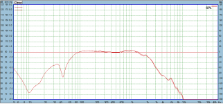
I've attached quick comparison using the SB Acoustics SB15MFC which I happen to be currently working with to illustrate what I'm saying. One is using a zobel to flatten impedance with a second order network, the other is third order network and no zobel. Target response is LR4 @ 2200hz. I did this in 10 minutes so it isn't exact, but I think we can agree that zobel - as traditionally used - does nothing that can't be done without it. High frequency hash as you say is the same.
Now the phase response *may* not be exactly the same, but 1) you''l have to decide what works best on a case by case basis, and 2) if we prefer the phase response of the RC shunt we are really talking about tuning it in a way that really isn't a zobel as traditionally used.
Now the phase response *may* not be exactly the same, but 1) you''l have to decide what works best on a case by case basis, and 2) if we prefer the phase response of the RC shunt we are really talking about tuning it in a way that really isn't a zobel as traditionally used.
Attachments
augerpro said:if we prefer the phase response of the RC shunt we are really talking about tuning it in a way that really isn't a zobel as traditionally used.
... i agree to that, i seldom tune it for "flat impedance".
But i expect phase response and group delay to be more flat (compared to "electrical 3rd order lowpass" topology), even the changes in impedance i expect to be smoother, contributing to a more smooth impedance of the whole speaker ...
Even at the tweeter i would prefer the simple parallel resistor before going
"3rd order" unless matching the phase of both drivers at fc tells us we have to consider that ...
Last edited:
The SB15MFC has low inductance, zobel is mostly not needed for it. A driver with a higher inductance > 0.6mH will have more deviations from the intended function due to rising impedance. This does not take into account driver acoustic response, if you take the cheaper SB13pfc woofer, adding a tweaked zobel makes a perfect LR2 function ( 2.5-3Khz ) possible with a single inductor, also reducing the sharp cone resonanse peak, which can be adjusted with the value of the parallel resistor. A standard approach produces a more expensive crossover and sharper cone resonanse where the first would usually matter more to a commercial manufacturer.
- Status
- Not open for further replies.
- Home
- Loudspeakers
- Multi-Way
- can someone help me choose a crossover frequency