Hi Xp,
I'm slow, I need more explanation.
Why does the CCS not send 33mA to the lower leg?
How much current gets syphoned off to supply the base of Q1?
Where does the output settle if variable hFE pulls varying current out of the CCS load?
In other words, how does Q1 operate?
I'm slow, I need more explanation.
Why does the CCS not send 33mA to the lower leg?
How much current gets syphoned off to supply the base of Q1?
Where does the output settle if variable hFE pulls varying current out of the CCS load?
In other words, how does Q1 operate?
AndrewT said:Why does the CCS not send 33mA to the lower leg?
How much current gets syphoned off to supply the base of Q1?
Where does the output settle if variable hFE pulls varying current out of the CCS load?
In other words, how does Q1 operate?
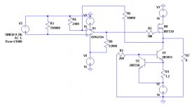
CCS does send about 33 mA into the base of Q1 and R1. Most of it goes into the base - only 0.7 mA goes through R1. The BE junction looks like a forward biased diode. Collector current of Q1 will be 32.3mA multiplied to the beta of Q1 - i.e. for b=50 Ic=1615 mA. However if beta is 100 than Ic=3230 mA. Variable hFE can not "pull a varying current" - the base current stays constant - but it will produce varying collector current.
Cheers
Alex
AndrewT said:thanks.
would performance deteriorate if the 1k0 were omitted?
Hi, according to the simulator, the circuit wont work without the 1k0 resistor.
AndrewT said:thanks.
would performance deteriorate if the 1k0 were omitted?
Not really, rather will improve a tiny bit 🙂
happyboy said:
Hi, according to the simulator, the circuit wont work without the 1k0 resistor.
Simulators are weird and wonderful things 🙂 .
Cheers
Alex
x-pro said:
Simulators are weird and wonderful things 🙂 .
Cheers
Alex
Haha okay. I realised that i simulated it the wrong way thats why it didn't work. Yep i would agree that they are wonderful but weird.
Hey guys,
sorry for bringing such a old thread.
To begin with, i have already completed this amp and i would really want to thank those people who have gave me comments and suggestions for the circuit. Thanks ALOT!
For now, i would like to bias the opamp in the circuit to class A with a 52K resistor. According to the simulator, i would get around 0.4mA of current flowing through when there is no signal. However, im not very sure if would it work in this manner in real life. Perhaps u all can guide me once again?
Thanks!
Attachments
Hi,
charging 160pF to 20Vpk @ 20kHz requires 0.4mA.
How does one calculate the output current requirement to feed a FET load?
When a resistor is used for the enforced ClassA output, is the maximum available current equal to half the standing current?
If a CCS is used to load the opamp output stage, does the full standing current become available to drive the load?
AndrewT said:Hi,
charging 160pF to 20Vpk @ 20kHz requires 0.4mA.
How does one calculate the output current requirement to feed a FET load?
When a resistor is used for the enforced ClassA output, is the maximum available current equal to half the standing current?
If a CCS is used to load the opamp output stage, does the full standing current become available to drive the load?
I don't know how to calculate the output current requirement to feed a FET load but from what i see in the simulator, when i put the probe to measure the current going into the IRF530N, it reads a peak to peak swing of around +/-185nA.
As for the rest of the other questions u posted, i really dun have the knowledge to answer them😕
Hi,
unfortunately, I do not think M1 will in real life be properly driven by the opamp. I would invest in a dedicated driver with at least 10mA standing current.
unfortunately, I do not think M1 will in real life be properly driven by the opamp. I would invest in a dedicated driver with at least 10mA standing current.
- Status
- Not open for further replies.
- Home
- Amplifiers
- Solid State
- can someone help me check this circuit?