Hello, not sure if this is in the correct section, but will be used on a full range driver, so here goes.
Easy question, can i use normal audio capacitors and resistors? ie 250v or 10w.
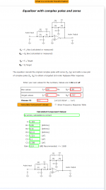
Maybe the hard one, what the hell is happening at the triangle symbol where a positive line becomes negative at point 2, then looks to become positive going to ground? Not too sure what the triangle represents, i think i understand the rest of it with a few more grounds than i'm use to.
Easy question, can i use normal audio capacitors and resistors? ie 250v or 10w.
Maybe the hard one, what the hell is happening at the triangle symbol where a positive line becomes negative at point 2, then looks to become positive going to ground? Not too sure what the triangle represents, i think i understand the rest of it with a few more grounds than i'm use to.
Attachments
the triangle is the OP-Amp symbol
Operational Amplifier
...the circuit is intended to make operate a woofer ( not a fullrange...) in a closed box ( or also in open baffle) and extend the lowest frequency capability.
It is intended to work at line level ( before the amplifier) thus the voltage and power of the passive components are kept 'low'.
Oh right....I'm having a hard time picturing that in my head. I get they part of the woofer and sealed box, so all good on that, i think I really need to see a picture of one set-up to fully comprehend it.
I want to use a 2.1 channel amp board which had a dedicated sub channel, so would the filter need to connect before it hits the board? And also go around it direct to the ground,?
I want to use a 2.1 channel amp board which had a dedicated sub channel, so would the filter need to connect before it hits the board? And also go around it direct to the ground,?
You'll be fine with 1/4w resistors and 10v rated caps.
It's basically an EQ tuned for a particular curve that will perfectly oppose the rolloff of a sealed box. IMO, not particularly useful - the room will dominate at low-frequencies anyway, so I'd rather correct for the speaker + room together.
Chris
It's basically an EQ tuned for a particular curve that will perfectly oppose the rolloff of a sealed box. IMO, not particularly useful - the room will dominate at low-frequencies anyway, so I'd rather correct for the speaker + room together.
Chris

A more precise definition of the Linkwitz transform
The Linkwitz transform is a circuit which applies two functions to the signal :
- an inverse function of the driver 2nd order transfer function around the resonance. Used alone, this inverse fonction would make the driver response flat at resonance and below.
- a new 2nd order function for the desired response.
Note that the Linkwitz transform can be used for mediums and tweeters to get the response of the filters more in accordance with their theory.
From the inventor of the LT himself:
Active Filters
How to set it up in a practical DSP solution using bi-quad filters:
Linkwitz Transform
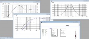
In a nutshell, the LT is the EQ function (green) that transforms the natural response (blue) to become the desired target (red) response, usually to achieve deeper bass extension at the expense of cone excursion - it is not "free extra bass" nothing ever is:

Active Filters
How to set it up in a practical DSP solution using bi-quad filters:
Linkwitz Transform
In a nutshell, the LT is the EQ function (green) that transforms the natural response (blue) to become the desired target (red) response, usually to achieve deeper bass extension at the expense of cone excursion - it is not "free extra bass" nothing ever is:
Back to the beginning. This circuit is to be placed before the power amp. In practice the resistors will be 1/4 w or smaller and the caps small film types probably rated 50v or less.
Also not shown is that small triangle part the opamp needs it's own power supply. In this case it probably needs something like + 15v and - 15v .
Also not shown is that small triangle part the opamp needs it's own power supply. In this case it probably needs something like + 15v and - 15v .
Nothing wrong with an LT if it's used correctly. Why Chris thinks they aren't particularly useful I've no idea and I'm sure Linkwitz would be the first to argue otherwise if he were still alive.
As Forr mentions they can be used with all types of drivers, tweeters, midranges, woofers, subwoofers, whatever. The point of the circuit is to take a sealed acoustic system, with less than optimum tuning and turn it into something more useful. This can be something simple, like modifying a tweeters roll off. Say the tweeter has an intrinsic fs of 1.2kHz and a Q of 1.1, but you want to cross it over with a 4th order LW slope at 3kHz. You can use the LT to modify the tweeters roll off to a target of 3kHz with a Q of 0.7. Having modified the tweeters response into something useful, you can simply apply a high pass with a Q of 0.7 and Fo of 3kHz to the tweeter and you'll arrive at your target of a 4th order LW at 3kHz.
You can use the LT circuit to raise and lower the tuning of a system. Or you can keep the tuning frequency the same but EQ out a high Q peak. Put a TG9 in a 1 litre cabinet and you'll get a Q of around 1.1. This isn't ideal. You can apply an LT to that system, keeping the tuning frequency of the system the same, but just remove the hump. This will actually increase the systems power handling around resonance and give you something better to listen to to boot.
Then, as you realise you don't listen to the system particularly loud, the drivers never get anywhere close to their linear excursion so you wonder well why not lower the apparent tuning frequency as well as getting rid of the hump? After all the system is bass light and it irks you quite a bit, but you don't have room for a sub.
Providing you lower the apparent tuning frequency with respect to the drivers capabilities there is no reason why not to do this. You have to pay attention to power handling, excursion limits, available amplifier power and maximum SPL to make sure you're actually using the driver correctly. But the end result is always, in my experience, much more pleasing with the LT than without.
For example see the attached image.
The blue curve is the aforementioned TG9 in the small 1 litre cabinet. Doesn't look very nice.
The black curve is the TG9 with a modest LT applied to EQ away the hump and extend the apparent tuning down to 80Hz. I have also applied a high pass filter to the driver at 50Hz with a Q of 0.7 to limit the lower bass from reaching the driver and protecting it from frequencies it cannot reproduce. When you are lowering a systems apparent tuning frequency using an appropriately designed high pass is almost mandatory.
At the levels you listen at with the LT in place the system sounds far more pleasing and you've made the most of the drivers capabilities too.
LTs are extremely useful tools for maximising system performance but they require care in their implementation.
Attachments
can one buy these premade?
I like the idea of trying to get the most out of the driver in a sealed enclosure, but must admit, scratching my head trying to understand how, if you put one of these before an amp how it only does it to the required channel. Or am i just overlooking the bit where the OPamp is now in play (being the triangular symbol). I had a look at a few spec sheets online and can see that you can hook power up to the VGC connections, which i could solder onto a board i intend to use.
I like the idea of trying to get the most out of the driver in a sealed enclosure, but must admit, scratching my head trying to understand how, if you put one of these before an amp how it only does it to the required channel. Or am i just overlooking the bit where the OPamp is now in play (being the triangular symbol). I had a look at a few spec sheets online and can see that you can hook power up to the VGC connections, which i could solder onto a board i intend to use.
Nothing wrong with an LT if it's used correctly. Why Chris thinks they aren't particularly useful I've no idea and I'm sure Linkwitz would be the first to argue otherwise if he were still alive.
In acoustically small rooms, the LF response deviates so far from the free-field response, that I find correcting the free-field response to be pretty much pointless.
For example, the speakers I'm listening to right how have a simulated (and measured at the cones) -3dB of about 50Hz. In-room, the response actually goes upwards (to +12dB) at 40Hz, and the -3dB point ends up at 10Hz.
So, I use EQ to cut down the large peak at 40Hz, and I get a nice flat in-room response. No EQ boost is necessary there, despite the theory.
To conclude, IMO it's applying a small correction to one part of a much larger problem. Better to fix the whole thing.
Chris
Ok, this is how i think this is put together, looking at those bug looking Opamps, i can see there is pins for AC power and other wonderful items.
I used HiFi Loudspeaker Design as the online calculator, put the driver in as how it would operate before any LT then applied the values to "boost" the signal and have come up with the following.
I will admit, i'm getting a tad bamboozled, but armed with a stylus and a tablet quickly drew up where i think it would go, with on the sub channel, used the red for positive and black for ground (with the exception of the power which green is pos and blue is neg).
How far am i off the mark?
Attachments
i can see there is pins for AC power and other wonderful items.
Opamps don’t have “AC” power pins. They require +/-voltage rails - clean ones. You will need a dual rail power supply probably at least +/-9v up to +/-15v. Two 9v batteries in series actually works well in a pinch for testing. Read the data sheet for your particular opamp. A very popular and good sounding one is NE5532. Important to install bypass 100nF x7r ceramic or film caps right near supply rail pins to ground (pins 4 and 8)
In acoustically small rooms, the LF response deviates so far from the free-field response, that I find correcting the free-field response to be pretty much pointless.
For example, the speakers I'm listening to right how have a simulated (and measured at the cones) -3dB of about 50Hz. In-room, the response actually goes upwards (to +12dB) at 40Hz, and the -3dB point ends up at 10Hz.
So, I use EQ to cut down the large peak at 40Hz, and I get a nice flat in-room response. No EQ boost is necessary there, despite the theory.
To conclude, IMO it's applying a small correction to one part of a much larger problem. Better to fix the whole thing.
Chris
This is completely missing the point.
Say you have a small sealed two way with a 5" bass driver in your room, it only goes down to ~80Hz.
Now lets say you change this for a slim floor stander with side mounted 8" bass drivers and it goes down to ~30Hz.
Intrinsically one has way more bass extension than the other. The one with side mounted bass drivers only manages this extension because it has internal amplification for the bass drivers and an appropriately designed LT. But to the person buying the speakers all they know is one has bass they find satisfying and the other does not.
Extending your view point it comes across as, don't bother building that 12" ported speaker with 20Hz extension, it doesn't correct for room integration issues so isn't useful. Also don't bother building those sealed subwoofers using 10" bass drivers and LTs to give 30Hz extension because they don't correct for room integration either.
The LT is limited because it doesn't solve the problem of room integration. Well obviously. It isn't supposed to solve the problem of room integration. It's like saying a high pass is limited in application because it wont boost bass frequencies, it isn't supposed to do that.
Yes the room dominates the frequency response within the modal region but this doesn't mean you throw out the box simulator and just cobble anything together. Might as well just put that 12" driver into a box of arbitrary volume and use a toilet roll tube as the port. The alignment doesn't matter at all because it doesn't correct for room integration. No.
You design the box and optimise it, accordingly, to provide you with the best performance that you can before any potential room integration EQ is to be applied. Deliberately under-sizing a sealed box and applying an LT to it, as part of that box design and optimisation process, is no different than designing any other type of box + driver combination.
As a perfect example Linkwitz used the original Peerless XLS drivers with a Qts of ~0.2 in his open baffle Orions, he then applied an LT to the system to raise the apparent system Qt up to 0.5. As far as I am aware he also raised the real fs from ~20Hz up to an apparent 40Hz.
If you want to apply additional EQ to the optimised system above then sure, go ahead.
To carry on...
For example, the speakers I'm listening to right how have a simulated (and measured at the cones) -3dB of about 50Hz. In-room, the response actually goes upwards (to +12dB) at 40Hz, and the -3dB point ends up at 10Hz.
So, I use EQ to cut down the large peak at 40Hz, and I get a nice flat in-room response. No EQ boost is necessary there, despite the theory.
Bold is what I added.
What theory predicted that? You already had speakers that extended down to 50Hz in box simulation. Additional simulation would have shown that when placed in room you'd get a gentle lift, extending the bass extension below 50Hz and that you'd get a huge peak at around 40Hz due to a room mode. Theory would predict that you'd need a notch filter to remove the influence of said room mode. Not the LT.
If you had sealed speakers with an f3 of 120Hz and wanted extension down to 30Hz, with a suitable driver, enough amplifier power and modest SPL requirements, the theory would predict that an LT would be a very good idea. Once you've extended the speakers bass extension it would then suggest that a notch filter would be a good idea to help with the room mode that you can now excite. This is how you use the LT. As a part of a whole to optimise a system.
What speakers are they by the way, that are giving you an f3 of 10Hz with a simulated f3 of 50Hz. I'm almost certain you haven't measured things correctly.
thanks for the responses. I dont suppose there is a site one could just buy one off the shelf 🙂
Well you can implement an LT with a miniDSP if you wanted a very easy way of playing around with active filter circuits.
There is this...
Linkwitz Transform Subwoofer Equaliser
You might be able to find thing elsewhere on the internet that you can buy.
Aargh!!! You need to check the NAME of this website!!!thanks for the responses. I dont suppose there is a site one could just buy one off the shelf 🙂
I forgot when you buy an amp board or driver off a website that is classed as diy, but realising that a LT filter is a bit much for an amateur isn't.
I wanted to give it a go, but I don't understand how it all interacts with the op amp, dual power etc and all I was wanting was to make a tiny BT speaker, don't really feel like electrocuting myself
I wanted to give it a go, but I don't understand how it all interacts with the op amp, dual power etc and all I was wanting was to make a tiny BT speaker, don't really feel like electrocuting myself
You won't get electrified, as the circuit needs very little power
Basically, it takes 5 minutes to mount the circuit on bredboard, 5 minutes to check if it's right.
Same for a basic power supply.
just use the basic precautions when working on the mains, one side of the transformer.You will need a dual rail power supply probably at least +/-9v up to +/-15v.
Basically, it takes 5 minutes to mount the circuit on bredboard, 5 minutes to check if it's right.
Same for a basic power supply.
For you purpose some bass boost in the form of tone control circuit before the amp is probably best. The Linkwitz Transform is too complex for your needs and requires knowledge of the speaker's parameters.
- Home
- Loudspeakers
- Full Range
- Can someone explain how this Linkwitz Transform works?