While I have you "on the line", so to speak, may I ask you another question on the same topic? Different project, but same concept. I guess I can hijack my own thread.
This is the input of a small Epiphone practice amp. Two things here I don't quite understand:
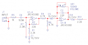
1. I'm trying to figure out the gain of U1-A. The formula is simple enough if C1 wasn't there. G=1+(Rf/Rin), which is 1+(22K/3K3) = 7.67. But I'm not sure how C1 (10uf) figures in there.
2. This is the part that's really messing with me. If you look at the volume control, (VR1), when it's turned down, it shorts out pin 6 to pin 7. I would think that that would put U1-B into unity gain. The output of U1-A is divided in half by R4/R6, and then whatever voltage is at pin 6 would have to appear at pin 7 by virtue of being a dead short. That signal would then go into the amp section.
But it doesn't. VR-1 is the volume control that kills the signal completely. There is no other level control downstream of R51. I just don't understand how that is happening, except that maybe my understanding of electronics isn't where I thought it was.
I'd appreciate any help in understanding these two issues.
This is the input of a small Epiphone practice amp. Two things here I don't quite understand:
1. I'm trying to figure out the gain of U1-A. The formula is simple enough if C1 wasn't there. G=1+(Rf/Rin), which is 1+(22K/3K3) = 7.67. But I'm not sure how C1 (10uf) figures in there.
2. This is the part that's really messing with me. If you look at the volume control, (VR1), when it's turned down, it shorts out pin 6 to pin 7. I would think that that would put U1-B into unity gain. The output of U1-A is divided in half by R4/R6, and then whatever voltage is at pin 6 would have to appear at pin 7 by virtue of being a dead short. That signal would then go into the amp section.
But it doesn't. VR-1 is the volume control that kills the signal completely. There is no other level control downstream of R51. I just don't understand how that is happening, except that maybe my understanding of electronics isn't where I thought it was.
I'd appreciate any help in understanding these two issues.
Attachments
> gain of U1-A. The formula is simple enough if C1 wasn't there. G=1+(Rf/Rin), which is 1+(22K/3K3) = 7.67. But I'm not sure how C1 (10uf) figures in there.
You need to look at a cap and guess if it shaves the bass, the treble, or neither (within the Audio Band).
10uFd with 1K resistor is "full bass" (17Hz). Higher resistor passes deeper bass. 10u and 3K is 6Hz. FAR below guitar band. So the 10uFd "is a Short" for all audio purpose.
Where does that leave you?
R6 is interesting because a clear analysis says it falls out of the gain equation. You have to look at OVERLOAD action to see why it is needed. Output of opamp A could slam input of opamp B so close to its rails that it gets ugly/nasty and not in a "groovy way". With R4:R6 the summing junction, "virtual ground", will not go to half-rail even when opamp B "virtual ground" has crapped-out.
PRR beat me to it 🙂
C1 has low reactance within the audio band and so may be considered a short circuit for audio. So your gain equation holds up for such AC signals.
As frequency falls the reactance of the cap becomes dominant and has the effect of rolling the gain off all the way to unity at DC.
The cap also stops the opamp amplifying its own DC offset errors as the voltage gain of the stage is unity at DC.
Also don't forget the input coupling cap. That also blocks DC and also adds a low frequency roll off as its reactance combines with the 2.2 meg resistor to form a high pass filter.
The active volume control is just an inverting stage where the feedback resistor is brought all the way to zero ohms.
R4 is the missing link for you understanding how it works. The gain is - (VR1/R4) the minus denoting an inversion of signal. So 100k and 4k7 gives a max gain of -21.2 numerically. With VR1 at zero ohms the gain is also zero.
C5 does the same thing... block DC. We don't want to be amplifying that.
R6 increases the 'noise gain' of the stage but has no effect on the gain calculation in real terms. It is not a divider (once the opamp is in circuit) although it might look like that at first glance.
It is a technique that can be used to aid stability although I'm not really sure why it was felt necessary tbh given the choice of opamp... however 🙂
Thanks PRR and Mooly. That helps tremendously. This is actually an "acoustic" guitar amp. It's intended to have a piezo pickup input. Which is why it has the really high input Z. However, it sounds great with a regular guitar input.
Thanks again guys.
Artie
Thanks again guys.
Artie
In the top diagram, is the basic input of an Audiosource AMP100, which is designed for +4 dBu pro level. The first thing the signal hits is an opamp configured as a voltage follower. (Unity gain.) If I want to convert the input to -10 dBV consumer level, is it as simple as adding the feedback circuit in the bottom half of the diagram? I have it set for a gain of 11, which is close enough to the 11.79 that I calculated.
Thanks all.
Artie
But -10dBV is an attenuation, not a gain. Your circuit amplifies, but going from +4dBV to -10dBV you need 14dB or a factor of about 5 attenuation.
Or 0.2 gain.
If I understand your question correctly.
Jan
Last edited:
No, this is an inverting stage, it's only non-inverting stages that are limited to unity gain. The output can send any amount of current to cancel the input signal getting to pin 6, without needing any output voltage to do it, as its shorted to it.2. This is the part that's really messing with me. If you look at the volume control, (VR1), when it's turned down, it shorts out pin 6 to pin 7. I would think that that would put U1-B into unity gain.
The voltage at pin 6 is zero as its an inverting stage so the inverting input is at virtual ground.The output of U1-A is divided in half by R4/R6, and then whatever voltage is at pin 6 would have to appear at pin 7 by virtue of being a dead short. That signal would then go into the amp section.
If I understand your question correctly.
Indeed.
But -10dBV is an attenuation, not a gain. Your circuit amplifies, but going from +4dBV to -10dBV you need 14dB
This was thrashed last year. It is not "+4dBV" but +4dBu.
-10dBv is 0.316228V. +4dBu is 1.228292V.
If the INput is intended to eat 1.22V, but you can only offer 0.3V, then your INput needs additional gain. 1.228292/0.316228 is "4" for any practical purpose. For educational or government purpose use "3.88".
- Home
- Source & Line
- Analog Line Level
- Can someone double-check my opamp FB theory?