I will use a compression driver in horn with the 10FE330, and it's still a raw plan. I'll only do the crossover when I have the cabinet. But a prestudy of that design says a fairly simple 2nd order should be possible with those. The SB26ADC tweeter is also fairly easy to work with (don't cross lower than 1500Hz altough) so that should probally also work.
But to be sure, measure the drivers in the cabinet and work from there. That is what i will do at the end.
But to be sure, measure the drivers in the cabinet and work from there. That is what i will do at the end.

I think that for such combinations (big mid bass - small tweeter) it is better to use a tweeter with a waveguide. Cutting the tweeter starts much earlier and it gets less energy at lower frequencies, and there is also a correction of the polar characteristic in that zone, so it fits better with the bass. Moving the tweeter back is also better for phase matching with mid bass on a flat front plate.
https://heissmann-acoustics.de/en/test-vifa-xt-300-xt25tg-waveguide-wg-300/
https://heissmann-acoustics.de/en/test-vifa-xt-300-xt25tg-waveguide-wg-300/
Example, 8"+1" in a closed box of smaller dimensions, the bass boom is controlled by one capacitor in line with the bass. Like KEF, which used to be done by others too, from that era. The goal was to get a deep bass from a smaller box. Everything is a compromise, of course, because that capacitor on the bass must be electrolytic.
https://heissmann-acoustics.de/en/disco-m/
https://heissmann-acoustics.de/en/disco-m/
Last edited:
It has been done before with a 10" and a small tweeter, like the infamous Dynaco A25 (probally the most sold speaker in the world). But you need a tweeter that can cross low (on it's own or with a waveguide) and a tuning that has a slow bass roll off to deal with room gain. Dynaco used an aperiodic porting for that (one of the reasons), but you can do that in a lot of ways. You don't need a smaller woofer for that (it's one of the ways).
I tend to tune my reflex cabinets in a way that the theoretical F3 in open air is more an F6 in that box, so when i put it in a closed space, the room gain get's compensated by that. You can do that again in a lot of ways, and each one has it's good and bad sides. My main system has sealed woofer now that have a F6 at 30Hz and are set at 20cm from the wall. That works because i took that in account in the design. You can also use aperiodic ported or closed with a lot of eq (best with dsp or analog line eq, not passive), ...
I tend to tune my reflex cabinets in a way that the theoretical F3 in open air is more an F6 in that box, so when i put it in a closed space, the room gain get's compensated by that. You can do that again in a lot of ways, and each one has it's good and bad sides. My main system has sealed woofer now that have a F6 at 30Hz and are set at 20cm from the wall. That works because i took that in account in the design. You can also use aperiodic ported or closed with a lot of eq (best with dsp or analog line eq, not passive), ...
Not so true anymore. Electronic Concepts makes what they call Unlytic UL30 (nonpolar polypropylene) capacitors in the standard 3" diameter case size. The film is stretched further to get more layers into the structure, and I've seen up to 1100uF values at 400VDC voltage rating. They can be very affordable on Ebay as NOS products. Yes, the 1100s are quite large.Everything is a compromise, of course, because that capacitor on the bass must be electrolytic.
Old solutions are with electrolytic caps. You can bypass that electrolyte with some film caps. You can also use polyester caps 100-150V, which are smaller in size, for mid bass it is acceptable. And a bigger box can be made, that would be the best. Or take a driver that fits a smaller box (smaller Qts) if the goal is a smaller box. Or apply the Isobaric principle, which gives a twice smaller box, but it is much more expensive. More bass is also expected with a smaller driver in a bass reflex box than a large one in a compression box, and the price is also lower. It is also easier to fit a smaller driver with a tweeter, the 3D sound image is better with a smaller front plate. The disadvantage of all smaller drivers is less efficiency. Some swear that bigger drivers sound better. There are many different solutions.
Last edited:
My bass drivers are 8" in 40l bass reflex (Vifa/Peerlees NE225W-08). There is too much bass at 20cm from the wall, however, even if I would eliminate it by closing the ports, I still have the problem of losing the depth of the sound image due to reflections from the wall between the drivers. That's why they stand 70cm from the wall. I also tried with mini monitors near the wall. I got some bass, but I lose the 3D image, which is the most important to me. Bass can be solved with an active SUB, the latter a bit more difficult.and are set at 20cm from the wall
Last edited:
I use Scanspeak 26W8534G00 in 77L sealed cabs and don't have the space for that distance. The back is at 20cm, the front at 50cm And the wall is drywall with 24cm rockwool between the two sides. So bass is largely damped by the wall itself. It's almost a bass trap. It may be that your room have roommodes that go high eough that it interferes with the mid and high. I use dsp to correct for the room, what helps a lot. When i had the same driver in reflex, i had similar problems with boominess, changing it to sealed solved that.
And 3D image is more in the highs and how wide the setup is set, where the illusion of space is created with reverb and timing differences. Woofers have little to do wit that, they just give support for that image (that is an illusion).
And 3D image is more in the highs and how wide the setup is set, where the illusion of space is created with reverb and timing differences. Woofers have little to do wit that, they just give support for that image (that is an illusion).
Yes, it is true that low frequencies do not create any 3D image, the wavelengths are long, there are a lot of weakly damped reflections in the room, and vinyl has low frequencies recorded as mono.
I didn't even think of that, but of reflections from the wall at medium and higher frequencies. The wall appears as a new source of sound and spoils the illusion of space. And I can't put damping there, there's my TV. I put a blanket over the TV, just for the test, and the effect is really good. 😁
I didn't even think of that, but of reflections from the wall at medium and higher frequencies. The wall appears as a new source of sound and spoils the illusion of space. And I can't put damping there, there's my TV. I put a blanket over the TV, just for the test, and the effect is really good. 😁
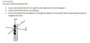
with 45mm plastic wave guide to tweeter to make Z = 0 mm and Y offset from -190 to -250 mm due to waveguide added. I need to increase tweeter L to 0.33mH as picture.
I think Z offset should be positive not negative due to woofer voice coil is 45 mm nearer to front wall (far away from Microphone).
due to my lack of knowledge waveguide solved problem of Z offset (+/-).
I think Z offset should be positive not negative due to woofer voice coil is 45 mm nearer to front wall (far away from Microphone).
due to my lack of knowledge waveguide solved problem of Z offset (+/-).
Attachments
The name of this chinese berrylium is F1-104NS RMB 360 per 1 piece has Fs about 600 can XO 1200-1400 hz cone brake up around 28K
PS. I have use both SB26ADC-04 and peerless XT25BG60-04 (with SDS-160F25PR01) these 2 tweeters are good but peerless can go low max as 2.2Khz otherwise distortion SB26ADC can go around 1.8K max (even Fs 550hz).
but F1*104NS is game changer can go 1.4Khz or even 1.2Khz which beats Dayteon RS28F that can XO around 1.5K
Last edited:
Hi A26RE4 Woofer ,you see this ? https://www.seas.no/index.php?optio...eas-a26-kit&catid=66:seas-diy-kits&Itemid=345Due to the graph is like CA18RLY which has cone breakup high?
Then can I make 2-way? With 91db tweeter vifa XT25BG60-04 which has fs about 600 hz
Dear mr. Waxx
Is z offset should be + instead of -?
Because voice coil of woofer move to front wall more than tweeter.
Is z offset should be + instead of -?
Because voice coil of woofer move to front wall more than tweeter.
Was confusing at first.Is z offset should be + instead of -?
Would assume - would indicate being further away from microphone. or - to move rear ward
It is not correct Z offset would be positive to represent further from mic.
Z [mm] is horizontal distance coordinate; negative closer to mic and positive further from mic.
With IEC baffle test, I assume drivers are tested 1 meter from baffle.
Do not know for sure, would like to know. If so then datasheet FRD/phase would account for voice coil distance.
If in theory everything test 1 meter from test baffle, not 1 meter from voice coil.
Thought many times if modeling should or should not include compensation for voice coil distance from baffle.
I dont know if IEC standard states test baffle or driver voice coil for 1meter test distance.
If baffle no compensation in model, if voice coil comp needed.
then many designers has specify value of Z such as this -45 mm. Why they add -45mm to program? I usually add + to Z if 6.5" I add around +28 to +30 mm.
Many designers also input Z value but negative. I am confused is Z in vituixcad should be + or -?
for 2 way I use tweeter position as origin of X Y Z axis adjust. Then If tweeter is top of woofer I add Y equal to "-" of distance of center of tweeter to center of woofer such as -180mm For Z, with no Waveguide in tweeter, I also add "+" to Z value of woofer.
Attachments

Last edited:
- Home
- Loudspeakers
- Multi-Way
- Can SEAS P25REX design in 2 way seal box?