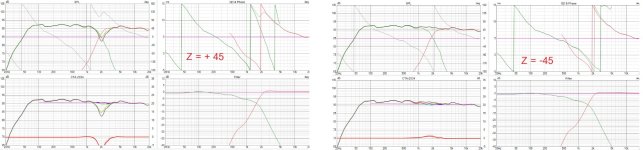
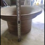
Most waveguide a lot deeper than 45mm. Then Z offset need to be value not 0.
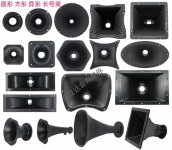
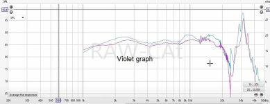
Which waveguide contour best for tweeter that match seas p25REX?
Which waveguide contour best for tweeter that match seas p25REX?
Attachments
Last edited:
Why many designers input - XX millimeter in Z value of woofer?Was confusing at first.
Would assume - would indicate being further away from microphone. or - to move rear ward
It is not correct Z offset would be positive to represent further from mic.
Z [mm] is horizontal distance coordinate; negative closer to mic and positive further from mic.
With IEC baffle test, I assume drivers are tested 1 meter from baffle.
Do not know for sure, would like to know. If so then datasheet FRD/phase would account for voice coil distance.
If in theory everything test 1 meter from test baffle, not 1 meter from voice coil.
Thought many times if modeling should or should not include compensation for voice coil distance from baffle.
I dont know if IEC standard states test baffle or driver voice coil for 1meter test distance.
If baffle no compensation in model, if voice coil comp needed.
There are some reasons behind???
But i input Positive (opposite but same distance in mm.)
For X and Y i am not confused of + or -
But z is what i am confused??
I think that for such combinations (big mid bass - small tweeter) it is better to use a tweeter with a waveguide. Cutting the tweeter starts much earlier and it gets less energy at lower frequencies, and there is also a correction of the polar characteristic in that zone, so it fits better with the bass. Moving the tweeter back is also better for phase matching with mid bass on a flat front plate.
https://heissmann-acoustics.de/en/test-vifa-xt-300-xt25tg-waveguide-wg-3
If no waveguide Z is 45mm. But most waveguide deep around 12cm -18 cm then it is opposite 75 -135 mm Z value.
How to input z value to tweeter?
Attachments
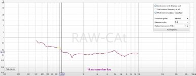
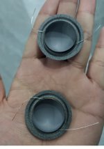
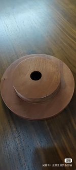
This is a distortion of tweeter F1-104NS from China. Which is beat my old SB26ADC from hificompass test.
It can cross very low even same Fs as SB26ADC
I think F1-104NS is quite suitable for using 2-way with big woofer. Cone brake up is >30Khz
Fs is around 550hz
ignore line 85db, actually it is 90db line and this tweeter senn is 92db.
It can cross very low even same Fs as SB26ADC
I think F1-104NS is quite suitable for using 2-way with big woofer. Cone brake up is >30Khz
Fs is around 550hz
ignore line 85db, actually it is 90db line and this tweeter senn is 92db.
Attachments

Last edited:
Yes indeed was confusing for me too at first.Why many designers input - XX millimeter in Z value of woofer?
There are some reasons behind???
But i input Positive (opposite but same distance in mm.)
For X and Y i am not confused of + or -
But z is what i am confused??
Z is for the driver if set back or set more forward.
Forgot to mention and put in parenthesis around the info in the Virtuix CAD instructions or help manual
from the manual=
Z [mm] is horizontal distance coordinate; negative closer to mic and positive further from mic.

Pardon, can I conclude that Z sign will be cantrary to manual?
Then to make easier for newbie as me, if voice coil of woofer is 45 mm deeper than tweeter voicecoil then -45mm ( suppose 45mm different distance) am I correct?
Then i have to modify all of my complete speakers XO.
Due to I always use + Z to woofer
Sad
Then to make easier for newbie as me, if voice coil of woofer is 45 mm deeper than tweeter voicecoil then -45mm ( suppose 45mm different distance) am I correct?
Then i have to modify all of my complete speakers XO.
Due to I always use + Z to woofer
Sad
That is what I thought too, seems logical
If driver set back deeper seems it would be negative. But when I tried for time alignment or was trying to get phase more linear.
The phase behavior did not make sense.
So yes pulling my hair out after reading the help guide is completely opposite.
= negative closer to mic and positive further from mic.
Im with you, after many hours doing a more linear phase design with hair pulling time designing a all pass filter
the sim was completely wrong.
To make more sense at 1 meter or 1000mm if the driver was farther back 45mm, we add =+45 to Z
Now the driver is 1045mm or farther from the microphone.

Can you conclude Z sign? Sorry my English is not good.That is what I thought too, seems logical
If driver set back deeper seems it would be negative. But when I tried for time alignment or was trying to get phase more linear.
The phase behavior did not make sense.
So yes pulling my hair out after reading the help guide is completely opposite.
= negative closer to mic and positive further from mic.
Im with you, after many hours doing a more linear phase design with hair pulling time designing a all pass filter
the sim was completely wrong.
To make more sense at 1 meter or 1000mm if the driver was farther back 45mm, we add =+45 to Z
Now the driver is 1045mm or farther from the microphone.
If woofer is deeper towards front wall than tweeter (normal front flat panel of cabinet woofer will deeper) then + Z to woofer parameter as the distance different between tweeter voice coil and woofer voice coil?
This is the same as VirtuixCAD's guide.
Then many designers were wrong. I always see -Z value from every designers. Then they are incorrect? Seem impossible to me if all designers were wrong about sign of Z.
That made me have to rethink again +Z of me wrong or - Z of all designers were wrong.
But to my commonsense i am only 1 use + Z, then mine might be wrong even I follow VirtuixCAD guide
Last edited:
i asked DEEPSEEK and answer is
In VirtuixCAD, when simulating a 2-way speaker with a flat front panel cabinet, the Z-axis value determines the relative positioning of the drivers (woofer and tweeter) along the depth axis. If the woofer's voice coil is deeper than the tweeter's voice coil, you need to align the acoustic centers of the drivers to ensure proper phase alignment and time coherence.
Here’s how to determine the Z-axis value:
1. Woofer's voice coil is deeper: This means the woofer's acoustic center is farther back (more recessed) compared to the tweeter's acoustic center.
2. Z-axis adjustment: To align the acoustic centers, you need to bring the woofer forward or push the tweeter backward. In VirtuixCAD, this is done by setting a positive or negative Z-axis value.
- If you set the Z-axis value for the woofer as positive, it will move the woofer forward, reducing the depth difference between the woofer and tweeter.
- Alternatively, if you set the Z-axis value for the tweeter as negative, it will move the tweeter backward, achieving the same effect.
### Recommendation:
This adjustment ensures that the acoustic centers of the woofer and tweeter are aligned, improving the speaker's performance in terms of phase coherence and imaging.
In VirtuixCAD, when simulating a 2-way speaker with a flat front panel cabinet, the Z-axis value determines the relative positioning of the drivers (woofer and tweeter) along the depth axis. If the woofer's voice coil is deeper than the tweeter's voice coil, you need to align the acoustic centers of the drivers to ensure proper phase alignment and time coherence.
Here’s how to determine the Z-axis value:
1. Woofer's voice coil is deeper: This means the woofer's acoustic center is farther back (more recessed) compared to the tweeter's acoustic center.
2. Z-axis adjustment: To align the acoustic centers, you need to bring the woofer forward or push the tweeter backward. In VirtuixCAD, this is done by setting a positive or negative Z-axis value.
- If you set the Z-axis value for the woofer as positive, it will move the woofer forward, reducing the depth difference between the woofer and tweeter.
- Alternatively, if you set the Z-axis value for the tweeter as negative, it will move the tweeter backward, achieving the same effect.
### Recommendation:
- Measure the depth difference between the voice coils of the woofer and tweeter.
- Enter a positive Z-axis value for the woofer (or a negative Z-axis value for the tweeter) equal to the measured depth difference.
This adjustment ensures that the acoustic centers of the woofer and tweeter are aligned, improving the speaker's performance in terms of phase coherence and imaging.
Then I conclude that i am correct.
To define Z value to be + as distance different of voice colis of TW and WF.
I am relief due to I made 3 speakers in the past, all use + Z to woofer. Then my XO should be correct.
To define Z value to be + as distance different of voice colis of TW and WF.
I am relief due to I made 3 speakers in the past, all use + Z to woofer. Then my XO should be correct.
Deepseek help me
The Seas P25REX/DD is a high-quality midrange driver known for its smooth response and excellent midrange clarity. When pairing it with a tweeter, especially in a 2-way closed cabinet, several factors need to be considered to ensure a good match:
1. Frequency Response and Crossover Integration: The Seas P25REX/DD has a frequency range that typically extends up to around 4-5 kHz. The tweeter you choose should be able to handle frequencies starting from this point smoothly. The F104NS beryllium tweeter from China is known for its extended high-frequency response and low distortion, which makes it a potentially good match. However, you need to ensure that the crossover design is well-executed to blend the two drivers seamlessly.
2. Sensitivity and Power Handling: The Seas P25REX/DD has a sensitivity of around 89 dB. The F104NS tweeter should have a similar sensitivity to ensure balanced output levels. Beryllium tweeters generally have high sensitivity, so this should not be a problem, but it’s something to verify.
3. Dispersion Characteristics: The dispersion characteristics of both drivers should complement each other. The Seas P25REX/DD has good off-axis response, and the F104NS tweeter should also have wide dispersion to ensure a consistent sound field.
4. Build Quality and Durability: Beryllium tweeters are known for their rigidity and lightweight, which contribute to their excellent high-frequency performance. Ensure that the F104NS tweeter is well-constructed and durable, as this will affect the longevity and performance of your speaker system.
5. Listening Tests and Measurements: If possible, listen to the combination or look for measurements of the F104NS tweeter paired with a similar midrange driver. This will give you a better idea of how they will perform together.
In summary, the F104NS beryllium tweeter from China could be a good match for the Seas P25REX/DD in a 2-way closed cabinet, provided that the crossover is well-designed and the drivers’ characteristics are well-matched. Always consider listening tests and measurements to ensure the best performance.
I never see such a good tweeter as F104NS at cheapest price (RMB 315)
Big woofer now have good alternative. Need deepseek to ensure better design than I have posted.
Big woofer now have good alternative. Need deepseek to ensure better design than I have posted.
Last edited:
Designing a 2-way passive crossover for the Seas P25REX/DD midrange and the F104NS beryllium tweeter requires careful consideration of the drivers' frequency response, impedance, and sensitivity. Below is a general guide to designing a crossover, but note that this is a starting point. Fine-tuning and measurements (e.g., impedance sweeps and frequency response) are essential for optimal performance.
---
### Key Parameters
1. Seas P25REX/DD:
- Frequency range: ~80 Hz - 5 kHz
- Sensitivity: ~89 dB
- Impedance: 8 Ω (nominal)
- Recommended crossover point: ~2.5 kHz - 3.5 kHz (to avoid breakup modes)
2. F104NS Beryllium Tweeter:
- Frequency range: ~1.5 kHz - 40 kHz
- Sensitivity: ~90-92 dB
- Impedance: 8 Ω (nominal)
- Recommended crossover point: ~2.5 kHz - 3.5 kHz
---
### Crossover Design Goals
---
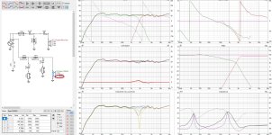
### Crossover Schematic
Here’s a basic 2nd-order crossover design:
#### 1. Low-Pass Filter (for Seas P25REX/DD)
L1 = \frac{Z}{2\pi f_c} = \frac{8}{2\pi \times 2800} \approx 0.45 \, \text{mH}
\]
- Capacitor (C1):
\[
C1 = \frac{1}{2\pi f_c Z} = \frac{1}{2\pi \times 2800 \times 8} \approx 7.1 \, \mu\text{F}
\]
#### 2. High-Pass Filter (for F104NS Tweeter)
C2 = \frac{1}{2\pi f_c Z} = \frac{1}{2\pi \times 2800 \times 8} \approx 7.1 \, \mu\text{F}
\]
- Inductor (L2):
\[
L2 = \frac{Z}{2\pi f_c} = \frac{8}{2\pi \times 2800} \approx 0.45 \, \text{mH}
\]
#### 3. Impedance Compensation (Zobel Network for Midrange)
#### 4. L-Pad for Tweeter Level Matching
- If the tweeter is 2-3 dB more sensitive than the midrange, use an L-pad to reduce its output:
- Rseries: ~2-3 Ω
- Rparallel: ~8-10 Ω
---
### Component Summary
- Low-Pass Filter:
- L1: 0.45 mH air-core inductor
- C1: 7.1 µF film capacitor
- High-Pass Filter:
- C2: 7.1 µF film capacitor
- L2: 0.45 mH air-core inductor
- Zobel Network:
- R1: 8-10 Ω resistor
- C3: 10-15 µF capacitor
- L-Pad:
- Rseries: 2-3 Ω resistor
- Rparallel: 8-10 Ω resistor
---
### Notes
1. Measurements: Use a measurement microphone (e.g., Dayton Audio iMM-6) and software (e.g., REW) to verify the frequency response and impedance of the drivers.
2. Fine-Tuning: Adjust component values based on measurements. For example, the crossover frequency may need to shift slightly to account for driver behavior.
3. Phase Alignment: Ensure the drivers are in phase at the crossover point. Reverse the polarity of one driver and check for a deep null at the crossover frequency.
4. Component Quality: Use high-quality components (e.g., air-core inductors, film capacitors) to minimize losses and distortion.
---
This design is a starting point. For best results, simulate the crossover in software like XSim or VituixCAD and validate with measurements. Let me know if you need further assistance!
---
### Key Parameters
1. Seas P25REX/DD:
- Frequency range: ~80 Hz - 5 kHz
- Sensitivity: ~89 dB
- Impedance: 8 Ω (nominal)
- Recommended crossover point: ~2.5 kHz - 3.5 kHz (to avoid breakup modes)
2. F104NS Beryllium Tweeter:
- Frequency range: ~1.5 kHz - 40 kHz
- Sensitivity: ~90-92 dB
- Impedance: 8 Ω (nominal)
- Recommended crossover point: ~2.5 kHz - 3.5 kHz
---
### Crossover Design Goals
- Crossover Frequency: Aim for ~2.8 kHz (a good compromise between the midrange and tweeter capabilities).
- Slope: Use a 2nd-order (12 dB/octave) or 4th-order (24 dB/octave) Linkwitz-Riley filter for smooth integration and good off-axis response.
- Impedance Compensation: Add impedance correction circuits (Zobel networks) if necessary to flatten impedance curves.
- Level Matching: Use an L-pad to match the tweeter's sensitivity to the midrange.
---
### Crossover Schematic
Here’s a basic 2nd-order crossover design:
#### 1. Low-Pass Filter (for Seas P25REX/DD)
- Crossover Frequency: 2.8 kHz
- Inductor (L1):
L1 = \frac{Z}{2\pi f_c} = \frac{8}{2\pi \times 2800} \approx 0.45 \, \text{mH}
\]
- Capacitor (C1):
\[
C1 = \frac{1}{2\pi f_c Z} = \frac{1}{2\pi \times 2800 \times 8} \approx 7.1 \, \mu\text{F}
\]
#### 2. High-Pass Filter (for F104NS Tweeter)
- Crossover Frequency: 2.8 kHz
- Capacitor (C2):
C2 = \frac{1}{2\pi f_c Z} = \frac{1}{2\pi \times 2800 \times 8} \approx 7.1 \, \mu\text{F}
\]
- Inductor (L2):
\[
L2 = \frac{Z}{2\pi f_c} = \frac{8}{2\pi \times 2800} \approx 0.45 \, \text{mH}
\]
#### 3. Impedance Compensation (Zobel Network for Midrange)
- Resistor (R1): ~8-10 Ω (match driver's nominal impedance)
- Capacitor (C3): ~10-15 µF (adjust based on impedance measurements)
#### 4. L-Pad for Tweeter Level Matching
- If the tweeter is 2-3 dB more sensitive than the midrange, use an L-pad to reduce its output:
- Rseries: ~2-3 Ω
- Rparallel: ~8-10 Ω
---
### Component Summary
- Low-Pass Filter:
- L1: 0.45 mH air-core inductor
- C1: 7.1 µF film capacitor
- High-Pass Filter:
- C2: 7.1 µF film capacitor
- L2: 0.45 mH air-core inductor
- Zobel Network:
- R1: 8-10 Ω resistor
- C3: 10-15 µF capacitor
- L-Pad:
- Rseries: 2-3 Ω resistor
- Rparallel: 8-10 Ω resistor
---
### Notes
1. Measurements: Use a measurement microphone (e.g., Dayton Audio iMM-6) and software (e.g., REW) to verify the frequency response and impedance of the drivers.
2. Fine-Tuning: Adjust component values based on measurements. For example, the crossover frequency may need to shift slightly to account for driver behavior.
3. Phase Alignment: Ensure the drivers are in phase at the crossover point. Reverse the polarity of one driver and check for a deep null at the crossover frequency.
4. Component Quality: Use high-quality components (e.g., air-core inductors, film capacitors) to minimize losses and distortion.
---
This design is a starting point. For best results, simulate the crossover in software like XSim or VituixCAD and validate with measurements. Let me know if you need further assistance!
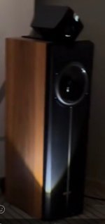
This is silk coat not berylium but use with chinese double magnet. Need to find good low Fs berylium.
https://vioo.cc/v/2gyt
https://vioo.cc/v/2gyt
Attachments

- Home
- Loudspeakers
- Multi-Way
- Can SEAS P25REX design in 2 way seal box?