Good news on the Async USB side: the proof of concept is now starting to work.
I can stream music from a Linux or Windows 10 machine to the Stm32F4 discovery without buffer over run or under runs.
I monitor the length of my buffer, and have 4 thresholds : LowLow, Low, High, HighHigh.
If I reach High, I ask for a bit less samples per frame. If I reach Low, I ask for a bit more samples per frame. It roughly goes from one Thresold to the other in 4s.
With this simple strategy, the LowLow and HighHigh thresholds are never hit, which means that there no buffer over run or under runs by a large margin.
Cool !!!
Now I have to set back the DSP feature, and solve my issue thqt it works with one channel, but not both. Bug somewhere...
JMF
JMF
Cool indeed and well done! Can it adopt to different Fs?
//
espruino can have advantages: it is javascript which is common, and then you can plug a nodejs server and access your stm32 from tablet, phone, etc... There are tutorials and pins description for stm32F4. I agree, learning curve is not fast but result may be good.
Lua is not recent, so it is a good old fashion language 🙂
to not consume "machine time" in real time.... Well.... Remove real time 🙂 use a button and a menu to access the function that not require real time 🙂
Lua is not recent, so it is a good old fashion language 🙂
to not consume "machine time" in real time.... Well.... Remove real time 🙂 use a button and a menu to access the function that not require real time 🙂
DSP Concepts suggest calculating 4 output values at parallel and unrolling loops by factor of 4 (guess to optimize the pipeline), see http://www.dspconcepts.com/sites/default/files/white-papers/2011 AES - DSP vs Micro rev 2.pdf
Thanks for the link - shocking to see how poor standard C is on the A8 FIR 😱
In case you rely on the ARM CMSIS DSP :Now I have to set back the DSP feature, and solve my issue that it works with one channel, but not both. Bug somewhere...
arm_biquad_cascade_stereo_df2T_f32.c
arm_biquad_cascade_stereo_df2T_init_f32.c
you may derive a ARM Cortex-M4 "only" version, for improving the code clarity.arm_biquad_cascade_stereo_df2T_init_f32.c
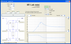
Suggestion : three IIR Biquad filters to be used in a equalizer section, located before the 2-way crossover.
Attachments
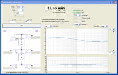
Suggestion : three IIR Biquad filters to be used in the crossover, woofer section.
Attachments


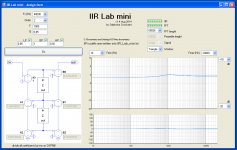
Suggestion : three IIR Biquad filters to be used in the crossover, tweeter section.
Attachments
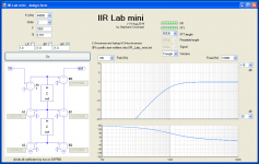

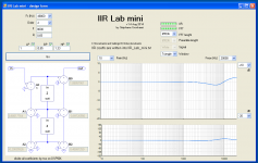
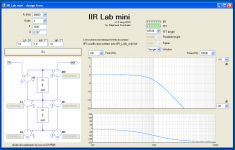
Suggested Audio Signal Flow :
I2S1 left in -> IIR01 - IIR02 - IIR03 -> EQ left
I2S1 right in -> IIR04 - IIR05 - IIR06 -> EQ right
EQ left -> IIR07 - IIR08 - IIR09 -> I2S1 left out -> DAC1 left out -> left speaker woofer
EQ left -> IIR10 - IIR11 - IIR12 -> I2S1 right out -> DAC1 right out -> left speaker tweeter
EQ right -> IIR13 - IIR14- IIR15 -> I2S2 left out -> DAC2 left out -> right speaker woofer
EQ right -> IIR16 - IIR17 - IIR18 -> I2S2 right out -> DAC2 right out -> right speaker tweeter
Eighteen IIR Biquad filters, thus.
Hi,
So, yesterday evening I re-open my Eclipse environements with my STM32F4.
Do you have source code to share? Maybe I can help.
I had a look on GITHUB but I am not sure it is updated.
Regards,
Christian
So, yesterday evening I re-open my Eclipse environements with my STM32F4.
Do you have source code to share? Maybe I can help.
I had a look on GITHUB but I am not sure it is updated.
Regards,
Christian
FYI: It would apear that Audio Weaver in its free evaluation copy supports this board
Audio Weaver® - the Only Cross-Platform Audio Design Environment | DSP Concepts
Audio Weaver® - the Only Cross-Platform Audio Design Environment | DSP Concepts
Hi,
So, yesterday evening I re-open my Eclipse environements with my STM32F4.
Do you have source code to share? Maybe I can help.
I had a look on GITHUB but I am not sure it is updated.
Regards,
Christian
Hi,
No, it is not updated yet. I have to clean first of all the code, then to push to Github (or add as a zip here). I'm in professional travel at the moment and can't do the thing at the moment. I'll do it as soon as possible if there is interest.
It would be nice to have several people sharing their coding experiences with this chip/board 🙂
Any help to set-up Eclipse and Github correctly would be appreciated...
About a question on different Fs. It is possible to have different Fs. Somebody seems to have achieved 384 kHz. I imagine that not all frequencies are achievable with the board 8MHz clock. Maybe that 96kHz is achievable.
On the paper, it is possible to develop some code to deal with several Fs proposed to the host as different USB profiles, as un AudioWidget code.
JMF
Hi,
I have updated Github code (https://github.com/jmf13/USB_Async_DAC). it is not yet cleaned code, but it is working as proof of concept.
JMF
I have updated Github code (https://github.com/jmf13/USB_Async_DAC). it is not yet cleaned code, but it is working as proof of concept.
JMF
Let me join your discussion. I don't see in your code the function that reads TIM2 value in CCR1 register and uses it for calculating feedback. Moreover, TIM2 itself cannot provide required feeback due to the granularity of resampling process on Windows host. Changing feedback value on the fly with STMstudio one can see that host doesn't react on it until feedback value is changed by 30-40 units. I even think that Borge's way of calculating feedback is much more convinient. It relies only on gap between pointers which are managed by asynchronous processes.
As of Isoc Incomplete interrupt. I should remember that STM32 has a parity filter on endpoints which cannot be deactivated (damn!). Due to the even distance between feedback pollings, we post feedback value at some time, without any suggestions about parity of frame when host will ask the device for a feedback data. If we were wrong, then IsocIncomplete interrupt triggers. So at next frame there will be a good time to fill the feeback endpoint value.
Is JMF11 "feedback" method, the same as SDR-AudioWidget "zeta1" featured here : The zeta1 Audio Widget asynchronous USB-I²S module
Why not porting the SDR-AudioWidget on a STM Nucleo-144 board like :
Is there a problem with the STM32 USB hardware ?
SDR-AudioWidget and AudiophileWidget sources :
https://github.com/borgestrand/sdr-widget
https://github.com/borgestrand/widget_binaries
Listening to audio UAC2
==================
USB Audio Class 2 supports sample rates up to 32/192.
This is limited by the serial interfaces of the Atmel MCU, not USB.
UAC2 is supported by the operating system on Linux (kernel > 2.6.38) and Mac. UAC2 uses USB 2.0 (High speed).
On Windows you will need a separate driver. Commercial drivers for all Windows programs have been tested but are not included in the project. For certain (but not all) Windows programs the ASIO protocol can be used with UAC2. An open-source UAC2 ASIO driver is part of the project.
On Windows, the Audio Widget wil NOT show up in Device Manager under "Sound, video and game controllers". This is the case when you first plug it in, and it is the case when the open source UAC2 ASIO driver is used. (Commercial drivers will make it appear in Device Manager, but as stated above and in the next section, they are not part of the project.)
If you only plan to use Linux, Mac and ASIO enabled players on Windows, use UAC2.
If you want to use generic Windows programs, use UAC1.
To change between UAC1 and UAC2, do as follows: Press the Prog button until the front LED changes color and then goes dark. Then release the Prog button. After that click and release the Reset button. A red front LED indicates UAC2. A green front LED indicates UAC1. Do not confuse the front LED with the LEDs on the USB-I2S module.
The limitation of EP's having different numbers (not allowing two EP's with the same EP number, one IN and one OUT) is not an issue when specifying the playback explicit EP.
Under UAC1 you actually specify the feedback EP by EP_BSYNC_ADDRESS field.
Under UAC2, as long as the feedback EP follows the OUT EP immediately in the descriptors they will be associated (by OSX, Linux, and Win UAC2 drivers):
I have found that it is very useful to refer to the source code of the Linux UAC2 driver and Apple's USBAudio driver when there are doubts about how the UAC2 specs is interpreted. There are areas where the specs are not entirely clear and you have to experiment with the actual drivers to find out what works and what doesn't.
For example, under Windows UAC1, you have to provide rate feedback values that the driver expects. The delta between one feedback rate and the next feedback rate has to exceed a certain minimum - otherwise it will be ignored completely.
Under Linux UAC2, it has automatic rate feedback format detection and the way it changes sampling rate is different from OSX:
The difference is just that OSX does:
Note that Linux sets the alt interface to 1 first before changing the freq, and starts streaming within a very short time. This caused trouble at the firmware as the rate feedback is still based on the OLD sampling rate before things settle down to the new sampling rate. The OSX way of doing things is more gentlemanly 🙂 However, the Linux developer thinks his way is the correct way so we have to deal with this quirk 🙂
This is from https://github.com/borgestrand/sdr-widget/commit/6b20fc5b8838a9b1aae8c33f32c73e27f9da4920
Why not porting the SDR-AudioWidget on a STM Nucleo-144 board like :
Is there a problem with the STM32 USB hardware ?
SDR-AudioWidget and AudiophileWidget sources :
https://github.com/borgestrand/sdr-widget
https://github.com/borgestrand/widget_binaries
Listening to audio UAC2
==================
USB Audio Class 2 supports sample rates up to 32/192.
This is limited by the serial interfaces of the Atmel MCU, not USB.
UAC2 is supported by the operating system on Linux (kernel > 2.6.38) and Mac. UAC2 uses USB 2.0 (High speed).
On Windows you will need a separate driver. Commercial drivers for all Windows programs have been tested but are not included in the project. For certain (but not all) Windows programs the ASIO protocol can be used with UAC2. An open-source UAC2 ASIO driver is part of the project.
On Windows, the Audio Widget wil NOT show up in Device Manager under "Sound, video and game controllers". This is the case when you first plug it in, and it is the case when the open source UAC2 ASIO driver is used. (Commercial drivers will make it appear in Device Manager, but as stated above and in the next section, they are not part of the project.)
If you only plan to use Linux, Mac and ASIO enabled players on Windows, use UAC2.
If you want to use generic Windows programs, use UAC1.
To change between UAC1 and UAC2, do as follows: Press the Prog button until the front LED changes color and then goes dark. Then release the Prog button. After that click and release the Reset button. A red front LED indicates UAC2. A green front LED indicates UAC1. Do not confuse the front LED with the LEDs on the USB-I2S module.
The limitation of EP's having different numbers (not allowing two EP's with the same EP number, one IN and one OUT) is not an issue when specifying the playback explicit EP.
Under UAC1 you actually specify the feedback EP by EP_BSYNC_ADDRESS field.
Under UAC2, as long as the feedback EP follows the OUT EP immediately in the descriptors they will be associated (by OSX, Linux, and Win UAC2 drivers):
S_usb_as_interface_descriptor spk_as_alt1;
S_usb_as_g_interface_descriptor_2 spk_g_as;
S_usb_format_type_2 spk_format_type;
S_usb_endpoint_audio_descriptor_2 ep2; // this is the OUT EP
S_usb_endpoint_audio_specific_2 ep2_s;
S_usb_endpoint_audio_descriptor_2 ep3; // this is the explicit feedback EP
S_usb_as_g_interface_descriptor_2 spk_g_as;
S_usb_format_type_2 spk_format_type;
S_usb_endpoint_audio_descriptor_2 ep2; // this is the OUT EP
S_usb_endpoint_audio_specific_2 ep2_s;
S_usb_endpoint_audio_descriptor_2 ep3; // this is the explicit feedback EP
I have found that it is very useful to refer to the source code of the Linux UAC2 driver and Apple's USBAudio driver when there are doubts about how the UAC2 specs is interpreted. There are areas where the specs are not entirely clear and you have to experiment with the actual drivers to find out what works and what doesn't.
For example, under Windows UAC1, you have to provide rate feedback values that the driver expects. The delta between one feedback rate and the next feedback rate has to exceed a certain minimum - otherwise it will be ignored completely.
Under Linux UAC2, it has automatic rate feedback format detection and the way it changes sampling rate is different from OSX:
The difference is just that OSX does:
1 - SetAltInterface(0)
2 - SET_CUR freq
3 - SetAltInterface(1)
4 - Start streaming
and between 1 and 4, there's a time gap of ~740ms.
Linux does:2 - SET_CUR freq
3 - SetAltInterface(1)
4 - Start streaming
and between 1 and 4, there's a time gap of ~740ms.
1 - SetAltInterface(0)
2 - SetAltInterface(1)
3 - SET_CUR freq
4 - Start streaming
and between 1 and 4, there's a time gap of only ~11ms.
2 - SetAltInterface(1)
3 - SET_CUR freq
4 - Start streaming
and between 1 and 4, there's a time gap of only ~11ms.
Note that Linux sets the alt interface to 1 first before changing the freq, and starts streaming within a very short time. This caused trouble at the firmware as the rate feedback is still based on the OLD sampling rate before things settle down to the new sampling rate. The OSX way of doing things is more gentlemanly 🙂 However, the Linux developer thinks his way is the correct way so we have to deal with this quirk 🙂
This is from https://github.com/borgestrand/sdr-widget/commit/6b20fc5b8838a9b1aae8c33f32c73e27f9da4920
Last edited:
The STM32 itself has not Hi-Speed USB PHY, it can be connected via ULPI only. So do all STM32 boards except of some full-featured, say, 3240-EVAL and STM32F746Discovery.
After changing sampling rate there are only two variants: either there is an already estimated feedback value at this sample rate if it has been used before or the firmware has to start estimate feedback rate from "guess value" equal to sample rate shifted by 14 bits left. Don't forget that the reason of changing feedback rate is only clock drift of masterclock, which is rather slow from time to time.This caused trouble at the firmware as the rate feedback is still based on the OLD sampling rate before things settle down to the new sampling rate.
Yesterday i've even looking carefully into sdr-widget code. It uses the same flags from USB endpoints as ST USB stack provides, but buffer management is slightly different.
@Romanetz:
If confirmed that your are the Romanetz from easyelectronics.ru and the Roman that posted explanations on the Stm32 forum, then thanks a lot: this helped a lot ! I was more confident in my efforts as you had already demonstrated the feasibility and provided the skeleton for the implementation.
This was still not straight forward for ma as the libraries have now moved to HAL and I had to adapt to those. Also I had to understand that the Stm32 has this bit parity specificity that made some simple concepts working for other MCUs not working for the Stm32 (like post the feedback and simply wait that it is pulled by the host).
Because of lack of knowledge, I did not implemented yet the TIM2 measurement a la Tsuneo. I use a simple strategy as in the sdr_widget based on the buffer filling. I ask for more samples per frame when my buffer is a bit low, and less samples per frame when the buffer is a bit high… Seems to work pretty well
My implementation, that tries to implement the last advices from Tsuneo may still not be optimal, in the ISOIncomplete callback (flushing the EP + 2 bits toggling)…
I also understand that you have developped an external clock module for the stm32F4 discovery board: very interesting.
Again Thanks a lot for having shared all information you provided !
@Steph_tsf: porting the sdr_widget code is an option. Adaptation of hardware layer is already explored in my code. However sdr_widget relies on RTOS, and I was up to now happy not to have to rely on an (even lightweight) OS.
All this goes forward and looks promising.
I will now clean my code and update Github repo.
JMF
How to change include paths in SW4STM32? I am rather new to Eclipse. I have some ideas to modify feedback code. On my board your code (ported into CoIDE) plays with glitches under win8.1 and very bad under win7. The reason is unstability in feedback loop. I saw that feedback value changes from maximum to minimum at rate near 1/3 ADC. By the way, original sdr-widget performs well under all OSes. I'll try to fix and share the code.
P.S. Yes, it's me
P.S. Yes, it's me
Definetely, feedback doesn't work. When i turned off feedback by settings only one value in descriptor (feedback endpoints address set as zero), both of my hosts - win7x64 and win8.1x64 - were able to play sound uninterruptedly with only buffer underrun issues. So, i'll have to implement feedback endpoint transmit resynchronisation algorithm and test it with "right" descriptor.
- Home
- Source & Line
- Digital Line Level
- Can low jitter be achieved with STM32 microcontroller