Another dumb question. What voltage rating should I use. The B+ is 879VDC and the B++ is 350VDC.
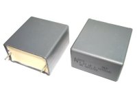
These are quite good caps (AVX brand, these caps are manufactured for industrial use) . If your driver stage runs at B++ of 350V DC and the cap is used to couple the driver to the (ground referenced) grid of the output tube, the cap will see 350V DC max. So your 1000V rating is more than safe.
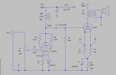
Yes, the grid of the GM70 is referenced to ground via R5. As the B+2 of 350 V DC is derived from the B+, you need a 1000V capacitor. During start up when all filaments are cold the full B+ of more than 800V may appear on the capacitor. It is also very important that the HT is coming up slowly to ensure that the GM70 filaments are fully heated up before the HT starts rising. Otherwise there would be an overshoot on the HT rising up well above 1000V. With the damper diodes as rectifiers you should be safe (the dampers heat up very slowly leading to a very smooth rising of the HT)
Acc. Table of dependence, You can use interstage cap about 0.82 uF, and that You can use and 0.47 or 1 mF......
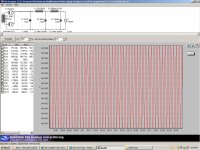
THanks guys. Yes, the warm up time on the 6D22S is 30 seconds. I just noticed I have not included the B++ leg on the PSU Designer II graphic. I have to figure that out....which I "think" will cause some heat build up somewhere to reduce the Vs from 841v to 350v.
I'm a bit worried about the high voltage aspect of the design since you are a bit inexperienced. Do you understand the hazards involved? At 900V you are entering the realm of corona discharge and other random discharge phenomena. Insulation requirements are much greater at these voltages than for an amplifier operating at 400V..
How do you plan to trouble shoot in the event it does not work correctly, how will you measure the HV plate supply or will you? Are you equipped to measure things safely and understand how to do that?
What sort of components have you selected for the HV supply, and have you chosen an output transformer that is rated for continuous operation with combined 1500Vdc + Vac? (The driver will not provide sufficient grid current to get you more than about 1kVpp swing)
Sorry for all the questions, I just want to make sure you get to enjoy the amps beyond the first moments you turn them on to start troubleshooting.
THanks guys. Yes, the warm up time on the 6D22S is 30 seconds. I just noticed I have not included the B++ leg on the PSU Designer II graphic. I have to figure that out....which I "think" will cause some heat build up somewhere to reduce the Vs from 841v to 350v.
I strongly recommend you not do this, and use a second transformer instead and associated supply, it's much safer and will allow for some basic trouble shooting without the high voltage B+ being present. (This is what I did in my GM70 amps, noting that I have never directly measured the 1kV+ supply - I don't even operate them with the covers removed.)
Thanks Kevin, I certainly appreciate your concern. I was a Radioman in the Navy and worked with much greater voltages than this while performing maintenance on the radar systems.
I have an Oscope and a good high voltage Fluke DMM for testing.
I totally agree about a separate power supply for the 12GN7 and have the parts to build it, but unfortunately, I designed and built the amp before I thought about using a separate supply. I'll continue to figure out a way to shoehorn it into the excising space though.
Good to hear you are versed in high voltage circuitry, feeling much better now.
High voltage probe for scope might be a good idea if you need to look at output transformer waveforms - I've managed without so far.
Whose output transformer did you go with? I went with custom Electra-Prints about 6 yrs ago when I started my project.
High voltage probe for scope might be a good idea if you need to look at output transformer waveforms - I've managed without so far.
Whose output transformer did you go with? I went with custom Electra-Prints about 6 yrs ago when I started my project.
Haybour (sp) wound these specifically for this project. They are huge. Jack at electro print wound the plate chokes.
How would you describe your GM70 amp sound wise?
How would you describe your GM70 amp sound wise?
Good bass, quiet, detailed, lots of power reserve, very dynamic. (efficient speakers) Bandwidth is sufficient and into 8 -10 ohm resistive load meets 20 - 20kHz -1dB or better. Output impedance is several ohms.
It was designed as an experiment with transformer coupling, uses input and interstage transformers in addition to the usual output transformer. The driver is a D3A running at 20mA into a 1:1 (60H/30mA) amorphous core IT made by Monolith Magnetics.. Both the driver and output stage are fixed bias, B+ is 1kV @ 120mA. The output is Electra-Print 150mA/40W/7K:8, input is a UTC - A20.. The design is A1 only, but at one point I was thinking of A2 operation, it requires a lot more power than the D3A can deliver. At around 20W it just starts to gently go into compression, it never hard clips..
Power supplies and amps are on separate chassis for a total of 4 chassis.
Inputs are balanced over XLR balanced cables.
The system goes loud (north of 110dB at the listening position) you can't be in the room for an extended period of time at those levels.
I'm pretty happy with them, I've made a number of rather significant changes since I built them and I have not extensively remeasured anything since I did that, including a rather significant upgrade to a much more linear interstage transformer.
I have speakers which are ~100dB efficient, average power levels are under 10mW (not a typo). I've measured distortion at 100Hz, 1kHz, and 10kHz at 100mW as ~0.08% THD. I've also measured at 10W with the older interstage which was the dominant distortion source and at 100Hz/1kHz/10kHz measured about 1.5% THD.
Hum and noise are at least 75dB down relative to 100mW output. (Likely measurement system artifacts, because with inputs open there is no audible hum or buzz six inches from the woofers.)
I listen to everything from Tove Lo to Tchaikovsky and it handles it quite well.
I decided quite a while ago that because of the voltages involved I would not share this design with the forum.
Hi Jon. Do you mean C3? I have no idea to be frank. I am just following a schematic. What do you see as an issue?

- Status
- Not open for further replies.
- Home
- Amplifiers
- Tubes / Valves
- Can I use 1.1 instead of .47