As the title, I am looking to use a DIL spaced holes on a PCB to install some flying lead tubes for a 6N16B phono stage, but I don't want to hard wire them at this stage. The reasons are:
1. I don't know which way up I want to mount the valves, so would like the option of sockets that allow me to install on either side of the PCB (with an appropriate plug wired accordingly on both sides of course).
2. I don't know if the specified valve is the one I will end up using. The circuit is simple enough that I may adjust and use another subminiature type instead, I have a couple rattling around in the parts drawer. This being the case inevitably there is the issue of pin outs to consider.
Thoughts welcome - is there a better way to approach this issue?
Thanks in advance🙂
Hi,
Yes turned pin DIL8 only. I SAY that but the slightly wider 0.3 pitch are alright too, though generally in longer IC sizes. Can be cut but are brittle. I often cut then for single triode 5 SIL and it's annoying as breakage is high
I do that often with wire ended valves. It seems to work ok.
If the valve come with a wire protector at the base I generally leave them on and form the wires using those small plastic to--99 DIL formers.
I'll solder the wires into the turned pin socket and leave say 3mm to get a needle point iron tip in to solder.
It seems to work ok over the few months I've been doing it. I can't speak for how long they last ultimately
Last edited:
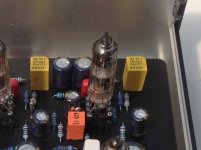
It works great.
Attachments
Last edited:
Yep just like that!
For the types I've used thus far, only power tubes (more risky perhaps?)
Satisfying the OCD I wa even able to put DIL pin 1 to tube pin 1 and make the pin no.s follow through to 8, missing 5 the cut off pin.
For the types I've used thus far, only power tubes (more risky perhaps?)
Satisfying the OCD I wa even able to put DIL pin 1 to tube pin 1 and make the pin no.s follow through to 8, missing 5 the cut off pin.
Got some 6n16b also, but haven't used any yet. I always wonder what to do with the other triode whilst setting up the first. Also it gets more awkward, 6n21b also has an extra screen pin, if I recall correctly
Messrs Mondogenerator and Koifarm,
Thank you for responding, most reassuring. Do you have a preferred DIL plug to use?
Mr Koifarm, I am talking about your mini-me circuit which I look forward to happily building when the bits arrive. Talking of which I have not found the mains transformer easy to source. Do you know where would you get one in the UK?
Got some 6n16b also, but haven't used any yet. I always wonder what to do with the other triode whilst setting up the first.
Also it gets more awkward, 6n21b also has an extra screen pin, if I recall correctly
Look at the links.
Mini-Me phono preamp
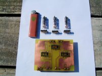
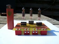
6N16 12x preamp srpp/cathode follower with printed circuit board design.
Source of my transformer.
2N1357 voedingstrafo voor buizenversterkers 48VA
You can use two transformers. One 50va isolation transformer with 2 x 115v secundairy and one with 12v/2a secundairy.
Yes, trafos 'made in England' but not available here ��
I got mine made a little smaller. Wrote an E-bay seller if he could get them made, and yes, 5-7 workdays, so guess he´ll be shipping them about now.
PRIM 0-115, 0-115
SEC 0-120v 40mA
0-120v 40mA
0-6,3v 1,2A
0-6,3v 1,2A
I ordered 5 pcs. and got them for 25$ a piece.
https://www.ebay.com/str/along1986090
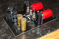
^That^ looks like a good improvement for longevity I reckon.
I have experienced tracking on FR clad board on onenoccasion, which i put down the temperature rise, and a bad layout in fairness but the proximity of 0.1" makes things tight.
The only thing I don't like is the longer tails
I have experienced tracking on FR clad board on onenoccasion, which i put down the temperature rise, and a bad layout in fairness but the proximity of 0.1" makes things tight.
The only thing I don't like is the longer tails
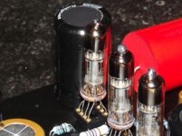
Is your PCB already made?
If still in the design stage, I´d modify it to use .156 pitch connectors.
**WAY** more robust , both electrically and mechanically, than puny .1" pitch one, way more than the pin to pin separation implies.
Large enough to solder wires to pins, or use insulation displacement connectors or later just hardwire them .
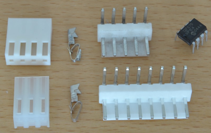
Top left terminals are calles "trificon" or similar, notice they have a miniature claw which strongly grips square posts; left bottom is the conventional one.
If still in the design stage, I´d modify it to use .156 pitch connectors.
**WAY** more robust , both electrically and mechanically, than puny .1" pitch one, way more than the pin to pin separation implies.
Large enough to solder wires to pins, or use insulation displacement connectors or later just hardwire them .
Top left terminals are calles "trificon" or similar, notice they have a miniature claw which strongly grips square posts; left bottom is the conventional one.
Last edited:
Thanks guys, the PCB is already made and I will give it a go. I have sockets that are good for the voltage (120v) and will over voltage and soak test it for a few hours before connecting to anything sensitive. Bit concerned that dust could precipitate tracking at a later time, what do you think?
Not at all, what makes you think that? I have better things to do than make posts on forums which waste other people's time without cause ��
I could and would have soldered the flying leads direct to the board unless I knew it was ok and prudent to do otherwise.
I could and would have soldered the flying leads direct to the board unless I knew it was ok and prudent to do otherwise.
Thanks guys, the PCB is already made and I will give it a go. I have sockets that are good for the voltage (120v) and will over voltage and soak test it for a few hours before connecting to anything sensitive. Bit concerned that dust could precipitate tracking at a later time, what do you think?
No problem here with dust over several years. Best connection is to solder them to the PCB and not use socket.
- Status
- Not open for further replies.
- Home
- Amplifiers
- Tubes / Valves
- Can I solder flying leads into a DIL plug?