Car lamp work for a current limiter or anything else heavy enough to do the job?
Where are the opto-couplers located on the board and the part number on them so I recognize them? Also is there a sub for them if blown?
Where are the opto-couplers located on the board and the part number on them so I recognize them? Also is there a sub for them if blown?
A headlamp will work. If you have to buy one, buy an H6054 and run both filaments in parallel.
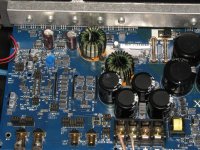
They are marked 3120 and are in the photo I posted.
They are marked 3120 and are in the photo I posted.
Got that lamp all wires up in that way just for that purpose better to ask and be sure too late if I am wrong
SST111 jfet there no NTE sub where do you track one of those down at?
SST111 jfet there no NTE sub where do you track one of those down at?
NEVER (<<< repeat NEVER) use NTE parts in car amps.
HCPL3120
HCPL-3120 Avago Technologies Logic Output Optocouplers
Why do you think the jfet is defective?
HCPL3120
HCPL-3120 Avago Technologies Logic Output Optocouplers
Why do you think the jfet is defective?
thanks Perry
that should get closer to finishing it and I will NEVER sub NTE parts even on the low power end of these amps.
I love a challenge well I guess I got one with this one I would been defeated if not for you Perry
Have a great weekend I know you made mine and hopefully the owner when finished as he calls it his baby...lol
All the best
Albert
No they are all original solder had never been touched. They was up playing around the mute Led because it was lit and had no amp output. they called xtant said it was in mute mode but did not know in the xtant tech section know how to bring it out of mute mode. That is why I asked about the shorting bars on accessory port #1. As I see there are no shorting plugs on the board I have but in the install manual shows one on either end of the pin strip plug. Can you send me a pic of that section of the board as I need to know as i don't know if that shop removed them or not? He took into a local shop that said they they could fix it and do that work and sell amps and car audio. Their the ones that made a mess of the amp and gave it back to him after charging him a high service charge up front when he dropped it off with them. that s the story on the amp and then he asked me if I would take a crack at it.
Thanks for the picture of that section that will answer about that acc# 1 shorting plugs question. While we are at it would you know its purpose?
Yes Perry referring to as the mute LED (LED236?) as that what the other shop said that xtant said it was for told him. Is that true Perry or is it not that at all and for something else? Do you know what it is an indication for when lit.
thanks
Albert
Yes Perry referring to as the mute LED (LED236?) as that what the other shop said that xtant said it was for told him. Is that true Perry or is it not that at all and for something else? Do you know what it is an indication for when lit.
thanks
Albert
on accessory port #1 in your picture shorting plugs are there and mine has none on it. That answers that question.
thanks perry
Albert
thanks perry
Albert
The LED is illuminated when the output stage is enabled (when the jfet is driven off).
I don't remember if those have to be on to allow the amp to produce audio. Maybe someone here that has experience with installing these amps can help. If not, try contacting xtant.
I don't remember if those have to be on to allow the amp to produce audio. Maybe someone here that has experience with installing these amps can help. If not, try contacting xtant.
Well Perry I have the protection circuit working cycling on and off and indicate so on the mute /protection LED with the headlamp as a current limiter and a 10 amp fuse in line no input signal and then after a few seconds cycles on and then shuts her down again. Tried it with the sub on the output with a 500 ma fuse inline to the sub for protection for the sub and no input signal. It comes on and cycles off again and the sub sucks in and stay in for a few seconds before the protection Led goes out or protection kicks in and she shuts down. The prtection circuit works as you said it should activate it takes a few seconds before new Jfet shut off and led lights and then goes out after about 5 to ten second. the system works fine now on the low end up to the optocoupler activate and they are fine. Also the protection system stays on with the optocouplers disabled and do not turn on the outputs and the outputs all checked good and reinstalled and mounted tight to the heat sink. I have not been in the power supply section yet. What should i check for voltages in this section and what components would you check first.
thanks
Albert
thanks
Albert
Did you try removing the outputs to see if there was a good (low frequency) drive signal on the gates of the FETs?
Did you replace the opto-couplers?
Did you replace the opto-couplers?
Put the output fets back in after checking them as I did not know I could run the unit with fets out and no speaker load in circuit. I pulled the opto couplers and it matter either one or both (I installed sockets for them) and as long as one was out of circuit the protection circuit would stay in the operational mode led lit.
So I can run it up with output fets out and scope gate signal if so can do I send and input signal in through my input jack to scope gate or is there a natural low frequency gate signal there at all times it is powered.
So I can run it up with output fets out and scope gate signal if so can do I send and input signal in through my input jack to scope gate or is there a natural low frequency gate signal there at all times it is powered.
The signal frequency will be directly related to the audio input signal.
You may have to bridge terminals 6 and 7 of the NE5532 (the one located between the two silver electrolytic caps) to get the drive signal to appear. Alternately (without the output FETs in the circuit), you may be able to short the positive and negative speaker terminals to accomplish the same thing. Don't do either unless the drive signal is absent.
Having the drive signal present on the gates isn't always a reliable indicator. Sometimes the opto-couplers are damaged but still work at low frequencies. They only cause problems when the amp begins to oscillate.
I didn't quite understand what you wrote about the protection circuit and the installation/removal of the opto-couplers. If there are no pull-down resistors on the gates of the output FETs or if they're out of tolerance, removing the opto-couplers could cause the over-current protection to be triggered. I think R246 is one of the pull-down resistors. It's connected in parallel to the 20v Zener. There is likely another one for the other opto-coupler.
- Status
- Not open for further replies.
- Home
- General Interest
- Car Audio
- Can I check hexfet out of circuit Xtant Amp