If so how is it done I working on a xtant xt1001 and have no schematic on it and would love to work on it and it been worked on before and need to any help I can get. It turned on the sub is driven full out and reverse the leads and the coil is full in . I suspect outputs but never worked on a Hexfet Amp before it acts like outputs and would like to check them.
been a tech for 36 years but this is a new animal for me hexfet
been a tech for 36 years but this is a new animal for me hexfet
HEXFET is a trade name. The transistor is nothing more than an N-channel, enhancement mode MOSFET.
When I check the fets they will turn on with DVM in diode checker mode. They should conduct(on) and non conduct (off) like a standard mosfet power fet? I see there is a zener added between sorce and drain inside them but they should check the same as the regular fets on or off with DVM in diode checker mode. The zener checks good but that is all that biases so the fets open(bad)?
Should read when I check regular mosfets power outputs they will turn on with DVM in diode checker mode.
Sorry about that these just check off
Sorry about that these just check off
I need a pic if the section of the amp board that has the mute Led as a couple smd semiconductors are not right. If anyone can help? They were changed and the other shop was guessing what they were as the had no schematic or cross numbers to go by and have way of knowing what the originals were so a pic would be very helpful. Also the original problem was it was in mute mode axtant told him over the phone as the led was lit they tell me and they said they said they did not know how to take it out of mute mode?
X1001 or XT1001?
Go to the FET section of the following page:
Basic Amplifier Repair - Transistor Test Applet Link
What output transistors are they using?
Go to the FET section of the following page:
Basic Amplifier Repair - Transistor Test Applet Link
What output transistors are they using?
Perry your the man🙂 thank you
they are using FB42N20D in the section I am working on
the help is very much appreciated
Albert
they are using FB42N20D in the section I am working on
the help is very much appreciated
Albert
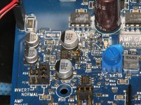
the section on the input side has the amp gain adjust,Q236,D262 ,Q221,R222 and LED 236 (mute led)
thanks
Albert
thanks
Albert
Resoldered the shunt resisters. The two resistors under the current shunt resistor R282. They are often in need of replacement or at least need to be resoldered. What are there values I will check them? Also Q236 and Q221 by the led 236 if I had the part numbers or the spec on them to sub them as the are not the correct one as to be in there as I suspected. You don't know there purpose in the circuit as very hard to figure without a schematic or voltages. Can I power this amp up with outputs pulled to work my way up to the finals and take voltages in the control circuits and power supply?
Thanks Perry
Albert
Thanks Perry
Albert
Also there are no shorting bars on the Accessory port#1 are there suppose to be 2 on either end as shown in installers reference literature pictorial from Xtant?
I don't understand what you're asking on post #12.
Download both the manual and hte reference sheet for the amp to see if they answer your questions.
Xtant Manuals & Installation Reference
Download both the manual and hte reference sheet for the amp to see if they answer your questions.
Xtant Manuals & Installation Reference
The two resistors under the current shunt resistor R282. that often in need of replacement or at least need to be resoldered. I need too what their ohm values as I will check them to see if their values are off?
Q236 and Q221 I need part numbers as 2N or 2S or PNP or NPN general purpose or specification on them to replace them as they are bad and voltages on their legs to know the ones I put in has the proper voltages to them as not to damage the new transistors.
Q236 and Q221 I need part numbers as 2N or 2S or PNP or NPN general purpose or specification on them to replace them as they are bad and voltages on their legs to know the ones I put in has the proper voltages to them as not to damage the new transistors.
R30 and R361 are 332 ohms. They are in parallel so you'll read 1/2 of the marked value.
Q236 is marked 1G which is an MMBTA06.
Q221 is likely marked C1 which would be an SST111 jfet. Leakage between the drain and source is normal for these transistors.
I don't know the voltages on their legs but the Vgs on the jfet is likely to be ~0v initially and ~15v after a few seconds. This transistor clamps the drive signal for the optocouplers.
Perry your just a wealth of knowledge with these car amps and I thank you for your time and patience with me.
I am very thankful for it
I have one more question can I with the amplifier outputs Digital audio output switching FETS removed power it and apply as input signal and scope it to make sure the audio and power supply signal and voltages is clean up to the outputs before installing the outputs in circuit as not to blow them out?
Albert
This is a self-oscillating class D amplifier so everything inside the feedback loop has to be in place for the amp to produce all of the signals you'd see when it's operating normally.
You can drive a signal into the amp and confirm that it reaches pin 1 and 5 of the NE5532 between the two electrolytic caps. If you solder a bridge between legs 6 and 7 of the NE5532, it 'may' produce drive signals to drive the opto-couplers. If it does, you would see a signal on the gates of the outputs but it would be at audio frequency, not at the normal carrier frequency (80kHz-160kHz, if I'm not mistaken).
You can drive a signal into the amp and confirm that it reaches pin 1 and 5 of the NE5532 between the two electrolytic caps. If you solder a bridge between legs 6 and 7 of the NE5532, it 'may' produce drive signals to drive the opto-couplers. If it does, you would see a signal on the gates of the outputs but it would be at audio frequency, not at the normal carrier frequency (80kHz-160kHz, if I'm not mistaken).
Is there a way to protect those outputs until I am sure it is stable and amp circuits are not over driving the output fets? Is there voltage checks in the source, gate and drain legs and bias currents to watch and check on the output fets?
The drive voltage for the outputs is determined by the voltage measured directly across pins 5 and 8 of each opto-coupler. It will generally be 15-20v DC. Do NOT slip when measuring the voltage across those pins. If you short to the other pins, it will destroy the opto-coupler.
To protect the FETs, clamp them tightly to the heatisnk and use a current limiter in the B+ line feeding the amp. It's not foolproof but it helps.
To protect the FETs, clamp them tightly to the heatisnk and use a current limiter in the B+ line feeding the amp. It's not foolproof but it helps.
- Status
- Not open for further replies.
- Home
- General Interest
- Car Audio
- Can I check hexfet out of circuit Xtant Amp