I searched, but I apologize if this question has already been asked.
The price of electrical wire has been increasing.
When making stators with wire, I think single-core UL1061 is one option.
For those who use single-core wire, what specifications of wire do you use?
Also, have you ever used copper-core binding wire?
On a side note, where can I buy toroidal transformers at a low price?
Hi,
PVC insulated single-strand/solid wire is the typically used wire for this application.
PVC has at least four favourable features:
Over here the typical naming of suitable wires would be H05-VU or H07VU.
Just get a source where the wire is preferrably heat treated ... it doesn´t break as easy when stretched straight ... and You need to stretch the wire just into the ´flowing regime´ of the material for perfect straightness.
Uninsulated wire should be regarded a nogo in a ESL.
jauu
Calvin
PVC insulated single-strand/solid wire is the typically used wire for this application.
PVC has at least four favourable features:
- easy and cheap to source ... great avaliability
- bulk resistance is rather on the lower side for a non-filled plastic
- epsilon-R is on the highe side for a non-filled pastic .... both parameters make it a trather good ´field conductor´ --> good efficiency of the stator
- PVC is relatively easy to glue
Over here the typical naming of suitable wires would be H05-VU or H07VU.
Just get a source where the wire is preferrably heat treated ... it doesn´t break as easy when stretched straight ... and You need to stretch the wire just into the ´flowing regime´ of the material for perfect straightness.
Uninsulated wire should be regarded a nogo in a ESL.
jauu
Calvin

I agree on the use of PVC insulated wire. Acoustat used a finely stranded 24 AWG, OFC copper. Insulation was 100% tested for 10 kV at the wire factory.
Hello, thank you for your response.
The copper binding wire has no markings on the sheath, is single-core, and has an outer diameter of 2mm (0.080").
I was hoping it could be used even though it is not an electrical wire, but I have decided to give up on using it.
Currently, I am trying to build a full-range speaker. Compared to others, I thought the UL1061 (AWG16), which has a thinner sheath, would be a good choice.
Unfortunately, although I heard that the markings are not very noticeable, the sheath always has some text on it.
I was not aware of the names H05V-U or H07V-U. After searching, I was able to find pages on Alibaba.com, among others. It was very informative.
Is "epsilon-R" a product name? I searched for it but couldn't find much information.
As a side note,
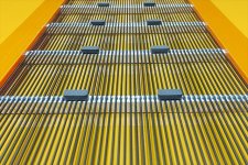
In the photo, I used "E6000" to bond polyethylene wires.
The copper binding wire has no markings on the sheath, is single-core, and has an outer diameter of 2mm (0.080").
I was hoping it could be used even though it is not an electrical wire, but I have decided to give up on using it.
Currently, I am trying to build a full-range speaker. Compared to others, I thought the UL1061 (AWG16), which has a thinner sheath, would be a good choice.
Unfortunately, although I heard that the markings are not very noticeable, the sheath always has some text on it.
I was not aware of the names H05V-U or H07V-U. After searching, I was able to find pages on Alibaba.com, among others. It was very informative.
Is "epsilon-R" a product name? I searched for it but couldn't find much information.
As a side note,
In the photo, I used "E6000" to bond polyethylene wires.
Attachments
And what is the point of this wire insulation, what does it give?
From my point of view, it is much better to put wires as thick as a wire with insulation, then the rigidity of the stators will increase and there will be less distortion.
In the case of thinner wires + insulation, this will be a harp, thin wires will bend in any case during active operation of the membrane, and will also steal the total area of the electrode.
The rigidity of the stators, in my opinion, is one of the fundamental rules for constructing an ESL. Where the stator is an anvil, and the membrane is a hammer that should fly off the anvil.
Hi,
havun, honestly??????
Asking that Q when it´d be potentially lethal to touch the wires ... which is always a accident waiting to happen with DIY or laboratory setups. 🙄
Stator rigidity certainly is a valid design point, but the more so is user safety ... especialy when starting the esl-route as a noob.
@Chace: epsilon-R is the dielectric constant which describes how many times higher the capacitance becomes compared to vaccuum, resp. air (epsilon-R=1).
PVC typically ranges around a epsilon-R of 4 and a volume resistance around 10exp12Ohm-cm
Now between Membrane surface and stator conductor lies the airgap and the counductor´s insulation.
These two series connected layers form a capacitive voltage divider under ac-conditions and a resistive divider under dc-conditons.
To achieve as small losses as possible and as much voltage across the airgap, the insulation capacitance should be high, hence a high epsilon-R.
Similar under dc-conditions the resistance of the insulation should be smaller than the airgap resistance to achieve a high field density in the airgap.
jauu
Calvin
I completely agree with your theoretical calculations, but unfortunately there are small discrepancies between the concepts of "should" and "is".
I have not seen an isolated stator in any Stax headphones, the stators in them are simply gold-plated so that the copper does not oxidize, their efficiency is very high.
Over 12 years of studying (amateur) in the construction of various electrostatic designs, I have tried many different options, now in my homemade design there is a high-frequency emitter with a very small radiation area and here there is a very big problem with the efficiency of this emitter, I have tried many options for stator insulation up to a special fluoroplastic varnish, different gaps (membrane-stator), different degrees of resistance of the conductive layer of the membrane coating and different bias voltages.
In the end, I settled on a gap of 2 mm and a NON-insulated stator (bronze mesh), in this ratio - the highest efficiency of the emitter.
I won't talk about the sound with a "bare" stator for high frequencies, it's better than with an isolated one, because I may be misunderstood.
That will always be a problem as long as you are operating in normal room air. Adding the proper stator insulation gets you user safety, more stable performance with varying humidity, more panel longevity, etc., but it cannot improve the basic output per unit area limitations imposed by the voltage breakdown limits of air. If you use the wrong kind of insulation you create new problems while increasing the required bias and drive voltages while simultaneously NOT improving voltage sensitivity or maximum output.with a very small radiation area
Here is one of the classic papers on insulation use by the person whose commercialized designs seem to have the longest lives:
The Technology of Full-Range-Element Electrostatic Loudspeakers, by James Strickland of Acoustat
https://www.izzy-wizzy.com/acoustat.pdf
Last edited:
The longevity of the panel from my observations is due to the higher resistance coating of the conductive layer of the membrane with which there is almost never a breakdown, all other things being equal.
The main problem in the construction of homemade electrostats is the application of a durable, uniform, high-resistance conductive layer on the membrane, but not reinforced insulation of stators, etc., the latter leads to a loss of sensitivity of the driver, this is my opinion.
Once again: the area of thick insulation can be filled with the active area of the stator-electrode, if we are talking about bars of wire, with equal acoustic transparency, will not this increase the sensitivity of the driver?
The Acoustat diaphragm coating was very good, which certainly helped with longevity. But if you look at the various Quad designs and their failure modes, there does seem to be evidence that a lack of insulation (or of adequate insulation) causes problems even with protection circuits, dust covers, and intentionally uncoated diaphragm areas in trouble spots.
If the volume resistivity and dielectric constant are set properly the insulation does not appreciably decrease output. The effective diameter of the wire becomes that of the insulation, so ultimately there's not much performance difference between a properly insulated wire of X diameter and a solid copper wire of the same diameter. Janszen's opinion in US patent 2,631,196 was that 92% of the signal voltage appears in the gap.
With round wires you do have variable distance from the conductor to the diaphragm though, so if maximum output is the goal large diameter wires are not as effective as something like a perforated plate with the same open area or a tight array of small diameter wires. That can make analysis more complicated than simple open area can describe. From a general design standpoint, the specific open area values I've seen suggested for maximum output were Harold Beveridge’s US Patent 3,773,976 at approximately 25% and David Hermeyer's 37% suggestion from the article “The Sanders Electrostatic Speaker” (1975 The Audio Amateur and reprinted in Audio Amateur Loudspeaker Projects).
- Home
- Loudspeakers
- Planars & Exotics
- Can binding wire be used for the stator?