First the question about grounding with the pot:
1. The ground end of the pot, (the minumum setting end) must read zero ohms to ground.
2. When you rotate the pot wiper to minimum setting, it must also read zero ohms to ground.
Please beg, borrow or whatever a DMM to check this before moving off to other matters so that we can get some understanding of what the likely problems are.
I assume the 250 Hz tone is a standard level test tone on a CD and it's at the same level as other frequency tones? Do other frequency tones have this resonance and is the effect similar at all output levels? Perhaps worse at high volume or low etc?
It would be premature to suggest causes of the resonance but this is quite an old receiver. If the caps and other deteriorated parts and connectors haven't been systematically renewed or otherwise cleaned thoroughly in the last 38 years, there could be many unknowable faults due to expired or at least very sick electrolytic capacitors. It also happens that over-enthusiastic guys fit monstrous caps because they can, but with no awareness of the consequences in some designs. Not all the old gear is built to the same basic designs with broad part tolerances - some units were quite touchy to incorrect parts, particularly around the tone controls, feedback and input paths. This one uses early type hybrid power modules (STK0040), so take it easy - they were generally quite easy to destroy in an instant of carelessness with speaker connections, meter probes etc. even with protection circuits.
So, if you haven't done it yet or only part done it, get cracking on an electrolytic recap program and only oversize the values where it is unimportant, like the main reservoir caps. decoupling caps etc. Otherwise, keep the enthusiasm down to +50% of the nominal capacitance values. Bear in mind that you are trying to solve a problem, not necessarily trying to spend every penny cramming it with capacitors and probably causing other, complicating problems that leave you confused as to what was/is wrong.
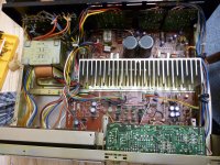
Thanks Ian, I do have a meter and will get back to you on those readings. It all has been cleaned thoroughly (see pic) and every connection the whole thing striped down and put back together all caps ESR readings are good if not excellent including their values. Both main boards where even switched from a donor unit and it was still doing it? I will get back to with those readings when I have time Thank you again.
Attachments
I suspect both the volume and "distortion" problem is nothing more than the unit having essentially DIN levels of input sensitivity (quoted as 160mv rms). A modern digital source such as a CD player is around 2 to 2.5 volts rms, thats more than 10 to 15 times too much. It should be easy to add permanent attenuators to the line inputs, either at the sockets if they are hard wired or by nicking the PCB print if they are directly soldered and adding a two resistor attenuator (two resistors per socket, one in series and one to ground).
Thanks mooly so I have been round and round for nothing? please can you give me details as to a way I can plug one into the phone inputs so I do not have to change the amp. Thanks.
You can either make them to fit externally like these,
Attenuators
or add them internally as a permanent fixture which is what I would do.
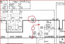
This shows one channels input (eg tuner left channel).
Also, if you dont use the phono stage then you could add a single attenuator to cover all inputs as shown. Change the value of R139 to say 22k and add a series resistor to ground, say 4k7). That would attenuate all inputs.
Attenuators
or add them internally as a permanent fixture which is what I would do.
This shows one channels input (eg tuner left channel).
Also, if you dont use the phono stage then you could add a single attenuator to cover all inputs as shown. Change the value of R139 to say 22k and add a series resistor to ground, say 4k7). That would attenuate all inputs.
Attachments

Thank you Mooly that is very helpful, so basically i can tag that first circuit in the end of a phono lead input and it will drop the voltage from the output player?
Yes, its just a simple resistive divider.
You could use a preset pot to experiment and get the values spot on (so the volume control feels right with level vs rotation) and then get the nearest fixed resistors to the setting.
You could use a preset pot to experiment and get the values spot on (so the volume control feels right with level vs rotation) and then get the nearest fixed resistors to the setting.
Hi mooly just to let you know I tried that first circuit with a trimmer pot, I could adjust the volume with it but unfortunately it made no difference to the problem I was having, strangely enough my jvc s77 does the same thing but at a lesser degree?
Hi mooly just to let you know I tried that first circuit with a trimmer pot, I could adjust the volume with it but unfortunately it made no difference to the problem I was having, strangely enough my jvc s77 does the same thing but at a lesser degree?
Hmmm... "sounds" and "noises" are difficult to diagnose without hearing them. Another wild guess, particularly as you mention another amp doing the same. Do these amps use relays to disconnect the speakers ? Tarnished contacts can give rise to very audible distortion/noise/level changes that is noticeable on a pure test tone. If you turn the volume up quite loud when this noise occurs and then turn it back down, is the noise the same or has it improved ? That can be a clue. The higher current actually "burns" through the insulating tarnish and works for a short while. I suppose the same issue could affect any mechanical switches in the signal path too, particularly any that carry the speaker currents.
That's a good suggestion, as it has happened to me somewhat as errol described. I had to ask for help the first time, since it was intermittent. The schematic shows a 4PST relay (RY401) with paralleled pairs of contacts on the JAS22. I imagine the 77 model is similar. If the case is open, a short clip lead of insulated wire and 2 croc./'gator clips is ideal for bridging out the supposedly closed relay contacts (one channel per bridge) for a quick check..... Tarnished contacts can give rise to very audible distortion/noise/level changes that is noticeable on a pure test tone....
JVC JA-S22 Manual - DC Stereo Integrated Amplifier - HiFi Engine
JVC JA-S77 Manual - Stereo DC Integrated Amplifier - HiFi Engine
Last edited:
Its happened to me too, and I couldn't quite believe it tbh. I went down the solid state route for switching and never looked back 🙂
Thank you the relay does seem a possibility since this is the only part which was not cleaned, Ian's suggestion is quite good but i must admit it makes me a little uneasy, i will take it out of the amp and clean the contacts, that should let me know if that is the culprit.
You can always link the relay out properly as a test (soldered links across it) so long as you connect speakers after powering up and disconnect them before switching off.
I would be more uneasy having removed the relay, cleaned and refitted it, only to find it wasn't the problem. I guess you will find out eventually, however you test it, when the contacts are sufficiently clean and closing squarely.
Still, I would be wary of repeated soldering operations on old Phenolic boards and urge you to resolder as little as possible. Usually, these relays have removable covers with small ribs acting as catches at the inner edge of the longer sides. A small blade will pop them in a few seconds and this reduces the potential for damage. If access is reasonable, you may be able to clean the contacts and snap the cover back on without need for removal or incident.
Otherwise, take great care removing and refitting it - use desoldering braid etc. and remove all solder - as there will be several, perhaps 10 contacts, to free completely before it will budge.
O.k so I tried to take the top off while it was in the amp and it would not budge, so I went ahead and removed it from the board. My soldering skills aren't to bad so I managed to get it out without issue. Unfortunately while levering it open I broke the relay..
Which was likely to happen. So now I need a new one of those. If you blokes could point me towards a new one on ebay, that is not from China I would be grateful. Thanks.
Which was likely to happen. So now I need a new one of those. If you blokes could point me towards a new one on ebay, that is not from China I would be grateful. Thanks.
So this is where we are i took the pcb out of the donor board with the unbroken relay, remember i said before it does exactly the same thing but this relay had an transparent cover as opposed to the other with a black cover and as such it popped off easily, and i cleaned the contacts with a sliver of paper doused in deoxit,, and guess what it now passes the frequency test with no resonating. So these sodding relays in all three units have exactly the same issue.
Thank you everyone for all your help i am really happy i managed to get it working again i never would never of guessed it was the relay.
now all i need to do is sort out that crappy volume pot
Thank you everyone for all your help i am really happy i managed to get it working again i never would never of guessed it was the relay.
now all i need to do is sort out that crappy volume pot
Thats great 🙂 Its a weird problem for sure and one I wouldn't have really believed... until it happened to me. On normal music there was no hint of a problem.
Great stuff !
Great stuff !
Hello mooly, It's true no one else in the family noticed a problem but i knew something did not sound quite right.
Here's a link to the most advertised source of the relay or at least a substitute part for that OEM JVC product. Needless to say, the originals probably have been out of production for as long as that series of amplifiers and the spares stock probably ran out long ago.
No, it's not a Ebay store but you did say Non-Chinese source?
No, it's not a Ebay store but you did say Non-Chinese source?
Hello mooly, It's true no one else in the family noticed a problem but i knew something did not sound quite right.
Yes, it's a strange one for sure. I couldn't hear any problem with mine if I'm honest, but on a sine wave yes, very noticeable. Turn the volume up and it "fixed" it for a while.
Here's a link to the most advertised source of the relay or at least a substitute part for that OEM JVC product. Needless to say, the originals probably have been out of production for as long as that series of amplifiers and the spares stock probably ran out long ago.
No, it's not a Ebay store but you did say Non-Chinese source?
How much 😀
I would look at the voltage rating and resistance of the coil and "make" a generic type fit. These are available for a couple of pounds. As you show as in the UK then check out the relays offered by CPC.
- Status
- Not open for further replies.
- Home
- Amplifiers
- Solid State
- Can anyone help with JVC JAS22