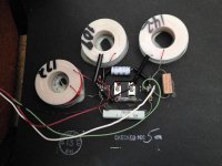
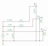
I got a pair of BIC SoundSpan TPR-600 that I got from a friend (who bought them new in the 70s). I was considering an XO upgrade or to go active, so I took a look at the original XO. But I can't wrap my head around it! Please take a look at the attached image. Red wire to woofer, green to mid and white to tweeter. They all share the black as the negative pole.
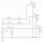
First of all, the markings on the coils; 109, 142 and 172? 109 can't be 10x10^9 so I'm a bit baffled. But what I find really puzzling is the fact that this 3-way XO only got one capacitor! The total amount of components and their values are; 1 capacitor 10uF, two resistors 2 and 4.7 Ohms, three coils marked 109, 142 and 172. I don't get it...
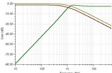
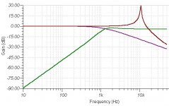
So I stuck the circuit with my assumptions into TINA-TI and ran a simulation. The circuit and the resulting graph are also attached. It sure didn't make me any wiser because it looks like the tweeter got a low-pass filter. What am I missing here? Has anyone ever seen a 3-way XO with only one cap? Or with a cap, two resistors and three coils in total? 😕
Thanks in advance for any help...
First of all, the markings on the coils; 109, 142 and 172? 109 can't be 10x10^9 so I'm a bit baffled. But what I find really puzzling is the fact that this 3-way XO only got one capacitor! The total amount of components and their values are; 1 capacitor 10uF, two resistors 2 and 4.7 Ohms, three coils marked 109, 142 and 172. I don't get it...
So I stuck the circuit with my assumptions into TINA-TI and ran a simulation. The circuit and the resulting graph are also attached. It sure didn't make me any wiser because it looks like the tweeter got a low-pass filter. What am I missing here? Has anyone ever seen a 3-way XO with only one cap? Or with a cap, two resistors and three coils in total? 😕
Thanks in advance for any help...
Attachments
Last edited:
Ps. I have learnt that the tweeter is a piezo and that it would explain the lack of a cap but I still don't get the coil for the tweeter? 😕
I started to write something, but I don't know what the vf1 vf2 and vf3 points are on the circuit, bypass for active??
It certainly doesn't look like a crossover for a three way. Maybe a 2.5 way?? But even if it were a 2.5 way the cap would be on the tweeter not the mid (is that labeled incorrectly?)
If the mid and tweeter labels are swapped then I would say it is a 2.5 way with 1st order electrical on the woofer and mid and a second order electrical on the tweeter...
Edit: ps. I'm not a guru! 🙂
Tony.
Last edited:
I am not a guru either, only a grown-up kid that likes to play around with loudspeakers.
I bet that tina-ti is required to be instructed where exactly it is supposed to take calculations, so the vf points define that.
I would advise OP to study the procedure of measuring FR and impedance, which can reveal the inductance values of unknown coils as well.
I bet that tina-ti is required to be instructed where exactly it is supposed to take calculations, so the vf points define that.
I would advise OP to study the procedure of measuring FR and impedance, which can reveal the inductance values of unknown coils as well.
The VF# are voltage points used to generate the graphs in TINA-TI (has nothing to do with the XO).
I think I got it now. This thread and this page gave me what I needed to figure it out. And this thread is giving me what I need to move forward. Thanks anyway for taking the time.
Ps. Still interested to know how to interpret the markings on the coils though.
I think I got it now. This thread and this page gave me what I needed to figure it out. And this thread is giving me what I need to move forward. Thanks anyway for taking the time.
Ps. Still interested to know how to interpret the markings on the coils though.
Why interpret something irrelevant, when you can measure directly the inductance. If you are interested in how to, let us know.
Pure curiosity (someone labeled them and probably for a reason, I want to know more if possible).Why interpret something irrelevant, when you can measure directly the inductance.
Yes, please share your knowledge.If you are interested in how to, let us know.
Ps. I have learnt that the tweeter is a piezo and that it would explain the lack of a cap but I still don't get the coil for the tweeter? 😕
I recommend measuring the capacitance of the piezo tweeter (and checking whether the diaphragm is still in one piece or shattered).
In the old days the capacitance of piezo tweeters was an object of controversy since some old amplifiers could not drive it directly without misbehaving.
The inductor, the internal resistance of the inductor, and the resistor can be considered a series network to increase impedance of the system at HF, above 20Khz. The peaking produced by the resonance of the inductor and piezo capacitance could be used too as boost for response correction at 10Khz to 20Khz.
Thank you Eva (will measure). I came to pretty much the same conlusion about the coil simulating with some wildly guessed values.
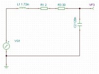
Schema of simplified eqvivalence of the piezo (the Motorola piezo is supponera to have an internal 30 Ohms resistor), first graph with coil, last without.
Schema of simplified eqvivalence of the piezo (the Motorola piezo is supponera to have an internal 30 Ohms resistor), first graph with coil, last without.
Attachments
Have you got a sound card/sound chip with a line/mic IN and line OUT?
If yes, then download ARTA, build a small impedance jig and let the device under test be an inductor. Perform impedance measurement with LIMP module and you will find out the unknown value.
Line IN lacking, and you'll need a multimeter to measure the voltage drops and perform a calculation. Basically a headphone OUT supplying a sine wave test tone to a network of two elements wired in series forming a closed circuit with it. Not just any rubbish MM, a decent one.
Can you do your tina simulation with the coil values as uH? ie 109uH 142uH and 172uH
The crossover makes somewhat more sense in light of the tweeter being a piezo 🙂
Tony.
The crossover makes somewhat more sense in light of the tweeter being a piezo 🙂
Tony.
Last edited:
Can anyone answer me why does Tina TI in a simple circuit consisting of one resistor and one inductor for example, shift the phase by -90 deg even though the voltage source of a sine wave is specifically specified at 0deg? The only phase shift there should be is the one resulting from these two components.
Forget my previous comment about the uH on a standard driver coils of that size have very little effect. I tried to find out more about this speaker, but apart from what it looks like (it is quite an unusual design), there is very little info.
Due to the configuration none of the normal modelling methods I would use would be of any help.
Tony.
Due to the configuration none of the normal modelling methods I would use would be of any help.
Tony.
You can use REW to measure the driver impedances.
Then use XSim to simulate each driver.
Make sure to measure the any open back drivers in the cabinet.
Then use XSim to simulate each driver.
Make sure to measure the any open back drivers in the cabinet.
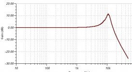
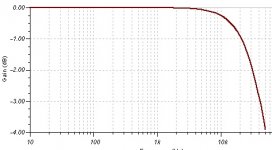
This thread @ Audiokarma contains pretty much everything you need to know about the piezo. The ones in the SoundSpan look identical to the ones in KSN1001A and KSN1005, so lets assume it appears as a 0.13 uF capacitor. Lets further assume the coils are 1.09, 1.42 and 1.72 mH and we end up with something like the attached files (lots of assumptions and simplifications but I think you get the idea). A first order filter on the bass with f3 ≈ 1.16 kHz, a second order filter on the mid with f3 ≈ 1.03 kHz and a notch on the piezo with the peak ≈ 10.74 kHz.
Attachments
- Status
- Not open for further replies.
- Home
- Loudspeakers
- Multi-Way
- Calling all XO gurus!