Hello, I am planning on using a pot as the load on the L/R outputs of a 100W 5.1 A/V receiver to feed to a more powerful pro-audio amp for the L/R mains.
100W max output power into 8 ohms comes to about 28 volts. The pro-audio amp can handle 13V peaks as a maximum. I can feed the amp peaks of about 6V if I use a 100k pot in the following configuration just for an example:

I read that the output impedance of a divider is the 2 resistors in parallel. If that is true I don't see how using a 100k pot in any audio signal chain would work unless it was feeding a preamp section with an extraordinarily high input impedance.
Am I looking at this right or am I missing something?
100W max output power into 8 ohms comes to about 28 volts. The pro-audio amp can handle 13V peaks as a maximum. I can feed the amp peaks of about 6V if I use a 100k pot in the following configuration just for an example:
I read that the output impedance of a divider is the 2 resistors in parallel. If that is true I don't see how using a 100k pot in any audio signal chain would work unless it was feeding a preamp section with an extraordinarily high input impedance.
Am I looking at this right or am I missing something?
Its right. In your example you will find the output impedance is 16.59k If you disconnect the 10k and measure the voltage at the pot 'wiper' (for any input voltage) you will get a certain value. Making the 10k a 16.59k (the value of 79k and 21k in parallel) will halve the voltage you see at the 'wiper'. As you can see, the output impedance varies with pot setting.
I would do this:
100 ohm load on the feeding amp speaker terminals. 1K in series with a 5K pot. Pot wiper to new amp input.
Now for safety put two 12v zener diodes across the second amp input in opposite polarity. This will clamp the input signal to no more than +/- 12v.
Since the source impedance of the feeding power amp is so low, you don't need a critical voltage divider.
But I must say a far better solution is to get a line level signal upstream of the first power amp.
EDIT: I like Gusser's idea also, and he typed faster.
Are you coming out of a speaker output, to another power amp's line inputs?
As the second amp probably has gain of 26dB, but can not have 26dB (400X power) more output, you are correct to pad-down. Assuming second amp is 4X power, 20dB would be a starting place.
If you are coming out of a speaker output, you can use much lower impedances and make stray effects more negligible. Take lower resistor as 100 Ohms. Then amp input of 5K or 500K makes "no" difference. 20dB is 10:1 voltage. Upper resistor figures at 900 Ohms (1K is probably close enough). Or make upper resistor 1K and select lower resistor 100r 150r 220r to taste.
EDIT again: Gusser's 100r loading on a 100W 8r amp should be 10W rated resistors. I'm undecided whether loading is needed; most modern amps are quite agnostic.
Last edited:
Making the 10k a 16.59k (the value of 79k and 21k in parallel)
The thing that I am confused on is this:
I was under the impression that the 16.59k would be the new output impedance that would feed the pro-amp's 10k input impedance. Higher output impedance than input being something to avoid.
How do I figure what the output impedance is feeding the final amp in the chain?
In a normal audio chain you might have a 50k pot (max output impedance 12.5k) feeding a 100k amp input. A 100k pot would do little harm. For a 10k input, as you have, a smaller pot value would be more appropriate. 5k would be fine.
16.59k is the output impedance of a pot set up as you show with a 79/21 split.
Normally we do always like to feed an input from a source impedance that is much lower than the input itself.
I'm not quite following you on the last bit.
The output impedance stays at 16.59k regardless of what you connect. In your example, the pot with no load would output a little over 0.2 volts peak for 1 volt peak of input signal.
If you now add your 10k load impedance then the voltage falls to just under 0.08 volts.
As proof of the output impedance still being 16.59k we can take a voltage source matching the output of the unloaded pot and give it a 16.59k source impedance. Again we would find that adding a 10k as a load would reduce the output to fractionally under 0.08v. The same result. The output impedance of both examples is still 16.59k
Why not better scale down the power using T or π networks, with lower resistance values?
Or still better, to get the signal before such an amplifier (The output class AB stage surely has higher distortion that will be further amplified by the following amp)?
Or still better, to get the signal before such an amplifier (The output class AB stage surely has higher distortion that will be further amplified by the following amp)?
Getting the signal before the amp output is not an option for reasons that I don't want to get into because it will clog the thread. I understand that doing that would have lower THD.
I'm just not seeing the math of how to break down the pot's output impedance to the amp pre's input impedance. Mooly, you seem to be explaining that the output impedance of the pot combines with the input impedance of the amp? I thought output and input impedances were separate from each other.
DF96, you said that a 50k pot has a max output impedance 12.5k... how are you calculating this? If the impedance of a voltage divider is the 2 resistances in parallel, wouldn't the max number from a 50k always be half of it's value -25k?
Making the 10k a 16.59k (the value of 79k and 21k in parallel) will halve the voltage you see at the 'wiper'.
79K in Parallel with 21K does Not equal 16.59K.
You can not Gain 2 significant Digits (.59) just like that.
More like 17K in the Math ?
Measured value may be different.
> Higher output impedance than input being something to avoid.
Why? Will something smoke?
We "usually" avoid that because loads may vary and hi-to-low will give different voltages. If everything were specified in current, hi-to-low would be natural. But incandescent lamps and tube grids are voltage-fussy, so historical power systems and audio systems are volt-centric, low-Z source hi-Z load.
> I don't see how using a 100k pot in any audio signal chain would work
Base rule of Dumb (workable) Design: pick your pot similar to your load. Knowing you had a 10K load, you should have picked a 10K pot. An 80:20 split would give a wiper impedance near 2K (1.7K). Loads 10K *and higher* will all get the same voltage within 20% or a couple dB. For any system with a user knob, 2dB of what you want is close-enough to avoid blasting or too-weak troubles.
Another issue: you want the *Line Impedance* to be low for good treble response and good crap rejection. 100 Ohms to 1K will take you far. In your plan, the line from wiper to power amp runs at 79K||21K||10K, a bit over 6K. Higher than I'd like, but generally low enough to run all over the house. However you note that other plans here lead to lower line impedance.
> wouldn't the max number from a 50k always be half of it's value 25k?
*Assuming* the source impedance is near-zero (often the case), then the half-way situation is 25K to ground *and* 25K to the low-Z source. Call it 13K (I don't want Art to say 12.5K is unwarranted accuracy).
> scale down the power using T or p networks, with lower resistance values?
In a low-to-high world, an L-pad will usually be better. I know the 3-R pads have mystic status because they derive from telephone and talking-movie work, but the situation was different then. A pi-pad is an L-pad plus an added resistor to load the source, but we can pick L-pad values to do any loading needed (often none). A T-pad is an L-pad plus a resistor to increase output impedance, and we sure do not need that.
79K in Parallel with 21K does Not equal 16.59K.
You can not Gain 2 significant Digits (.59) just like that.
More like 17K in the Math ?
Measured value may be different.
Not following you on that one.
Code:
1 1
----- + ----- = 16590
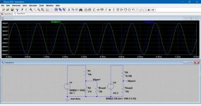
79000 21000This shows the 'pot' feeding a 10k load followed by a voltage source of 16590 ohms impedance feeding a 10k load. The First voltage source has 1 volt peak applied. The second voltage source is set to equal the voltage output of the unloaded pot i.e. 209.5 millivolts.
(phase shift added to make traces easier to see)
Attachments
Last edited:
There are two reasons for the 'usual rule' about pot output impedance being significantly smaller than load input resistance:
1. a low resistance load will distort the pot volume law - although sometimes this is wanted
2. input resistances can be non-linear, so feeding from a high resistance would create distortion
1. a low resistance load will distort the pot volume law - although sometimes this is wanted
2. input resistances can be non-linear, so feeding from a high resistance would create distortion
small correction : to allow for the source impedance seen by the vol pot as presented by the source (<150ohms).
Zout = 1/ {1/(79000+150) + 1/21000} = 1/ {0.12634/10^5 + 4.7619/10^5} = 1/ {6.0253/10^5} = ~16596r61
The extra ~6r61 is due to the Source Impedance of (the assumed Rs=) 150ohms.
Zout = 1/ {1/(79000+150) + 1/21000} = 1/ {0.12634/10^5 + 4.7619/10^5} = 1/ {6.0253/10^5} = ~16596r61
The extra ~6r61 is due to the Source Impedance of (the assumed Rs=) 150ohms.
Last edited:
Output voltage is lower side impedance divided by the total circuit impedance
Vout = Vin * 10k||21k / (10k||21k + 79k + 150r) = Vin * 6774.2 / (6774.2 + 79000 + 150) = Vin * 6774.2/85924.2 = Vin * 0.07884 (-22.07dB), as predicted by Mooly.
It helps when analysing a vol pot to consider it as a Jekyll and Hyde.
It behaves as a Receiver when connected to the source.
It behaves as the transmitter/source when connected to the load.
Analyse each side separately.
AND
remember each side MUST be connected with a two wire connection. i.e.
Source to vol pot is a TWO wire connection.
vol pot to Receiver/Load is a TWO wire connection.
Do not invent a "ground" and worse do not take this imaginary "ground" to some remote location where the introduced LOOPS will pick up interference.
The four wires coming into/out of the single channel vol pot are ALL Signal wires, none are "ground".
A two channel/stereo vol pot needs 8 wires. Again ALL are Signal wires.
Last edited:
Since it apparently hasn't been mentioned so far, you generally wouldn't be feeding the power amp a whopping 13 Vrms (which I guess is the maximum its pot could handle). 1.5 would be more like it. That's like what, 10k / 560R (1/4W MF)? Output impedance seems more reasonable like that.
100k Divider Measured
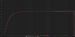
I figured I'd try the 100k pot just to document the results. Here is a graph of using a divider of 8 ohms (R1) and 1 ohm (R2) (white trace) vs. a 100k (actually 119k) pot set to 104.7k (R1) and 14.34k (R2) (red trace). Graph is set to 1dB scale:

I measured the output of the AVR amp at 9.98V and the output of the divider at 0.981V. The input impedance of the soundcard measuring the frequency response was about 4k. The high end was down -0.84dB at 20kHz and -0.27dB at 10kHz.
There was a 12 foot cable going out of the divider to the input of the soundcard.
I figured I'd try the 100k pot just to document the results. Here is a graph of using a divider of 8 ohms (R1) and 1 ohm (R2) (white trace) vs. a 100k (actually 119k) pot set to 104.7k (R1) and 14.34k (R2) (red trace). Graph is set to 1dB scale:
I measured the output of the AVR amp at 9.98V and the output of the divider at 0.981V. The input impedance of the soundcard measuring the frequency response was about 4k. The high end was down -0.84dB at 20kHz and -0.27dB at 10kHz.
There was a 12 foot cable going out of the divider to the input of the soundcard.
Attachments
Last edited:
14k output impedance feeding 12 feet of cable is just asking for treble roll-off.
Add a Buffer to drive that 12 feet of cable.
Sound card input impedance is much less than the source output impedance. Don't you listen to any advice from the Forum?
Add a Buffer to drive that 12 feet of cable.
Sound card input impedance is much less than the source output impedance. Don't you listen to any advice from the Forum?
- Status
- Not open for further replies.
- Home
- Source & Line
- Analog Line Level
- Calculating Voltage Divider (pot) Impedance...