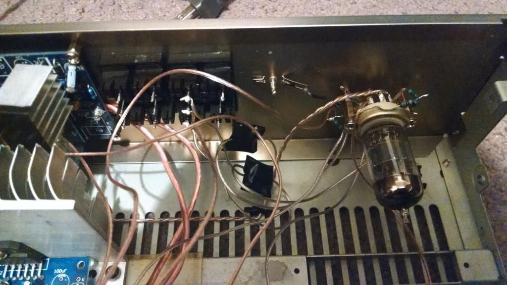
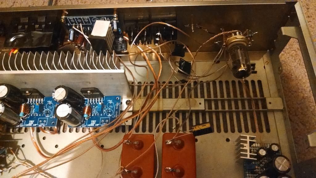
Many possibilities, can you post a schematic of the supply, and post a few pix of the layout?
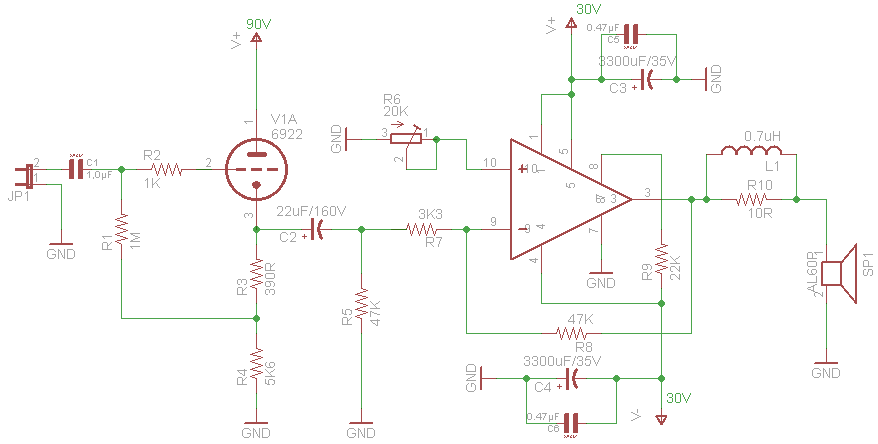
A 0.1uF in front of the CF would be sufficient as well. !!C2 is shown connected backward!!
Not sure why you went for an inverting input configuration, driving a 3.3K load is a pretty big deal for your 12AU7A, I am not certain it can provide the required current. A non-inverting configuration makes more sense and would probably result in less output offset. For minimum offset R6 should be in the vicinity of 24K, which will result in significantly more noise than necessary.
The trick is that I use 6922 tube here now. Sorry, it is not obvious and thread name is misleading...
R6 is actually 20K bourns pot that I have set to 3K3. I measure around 4mV at the output. But it is without tube connected. When tube is connected, voltage jumps from 2 to 15mV. Im assuming it is the ripple. I only have simple voltmeter.
Here is schematics with fixed capacitor, units for output inductor, and resistor trimmer for R6:
I also finished power supply schematics:
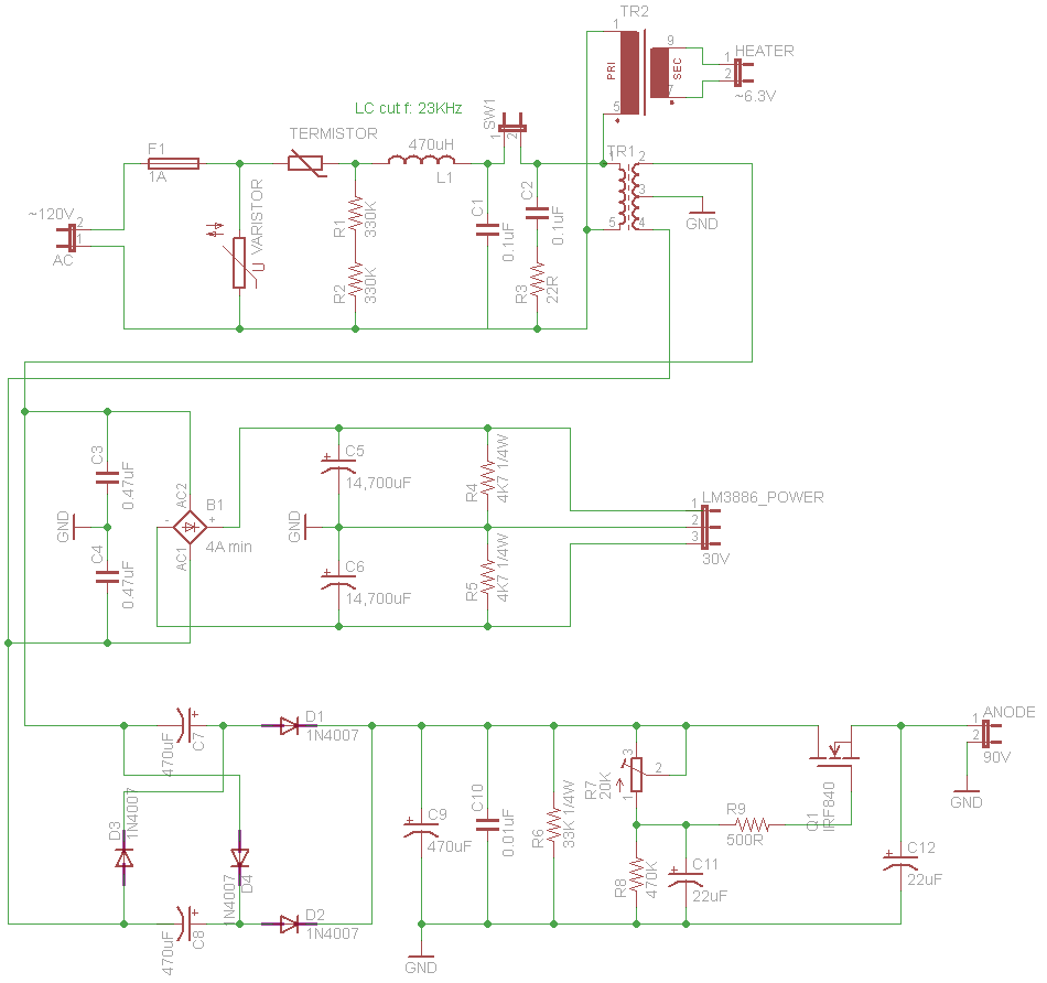
How did you determine the values of R4,5 & 6?
If these were larger, and you had a small resistor in series after each of the preceding smoothing caps I would expect to see less ripple for the same voltage supplied at +90, +30 & -30.
If these were larger, and you had a small resistor in series after each of the preceding smoothing caps I would expect to see less ripple for the same voltage supplied at +90, +30 & -30.
The tube circuit has only about 30dB supply ripple rejection. Confirm that your supply is clean. It should be, but check it. Other problems could be the earthing scheme or signal cables picking up hum.
Ripple has some higher harmonics on it compared to hum which is mains induced ( 50 or 60 Hz ). Ripple is twice that frequency plus harmonics. So if you are sure it's ripple I would check the supply first followed by the earthing scheme.
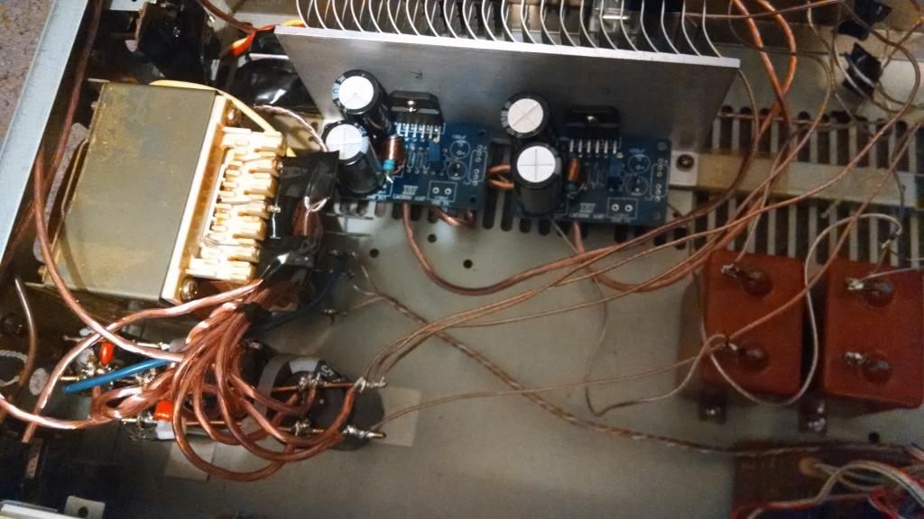
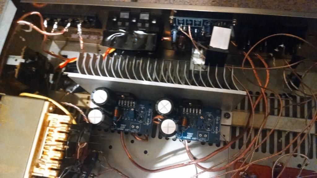
Just noticed the pictures.
Why didn't you place the supply caps between the Trafo and the power amp boards. Are you sure the trafo position isn't the cause , it looks awfully close ! Also oriented for worst case field alignment for the transformer.
Ripple has some higher harmonics on it compared to hum which is mains induced ( 50 or 60 Hz ). Ripple is twice that frequency plus harmonics. So if you are sure it's ripple I would check the supply first followed by the earthing scheme.
Just noticed the pictures.
Why didn't you place the supply caps between the Trafo and the power amp boards. Are you sure the trafo position isn't the cause , it looks awfully close ! Also oriented for worst case field alignment for the transformer.
Last edited:
- Status
- Not open for further replies.