For the non-inverting version you don't need a 'tube buffer', as any likely source will already have lower output impedance than the 'buffer' and much higher than the load. The 'buffer' will actually be an 'anti-buffer'.
For the inverting version you can't have a 12AU7-based 'tube buffer' as its output impedance will be similar to the load so will generate lots of distortion. You could try an ECC88 or similar high-gm valve, but an opamp buffer would be much better.
For the inverting version you can't have a 12AU7-based 'tube buffer' as its output impedance will be similar to the load so will generate lots of distortion. You could try an ECC88 or similar high-gm valve, but an opamp buffer would be much better.
OK. Let's talk about ECC88 then. What would be resistors values for it? Load impedance 980 Ohm, source signal CD or iPod. 90V anode supply. Same schematics:
An externally hosted image should be here but it was not working when we last tested it.
You need to specify what your aim is i.e. how much distortion on signal peaks? If your aim is 'as little distortion as possible' then you wouldn't be using a tube buffer into such a low impedance. Knowing how much distortion you want, you can then choose a load line which will provide it.gooduser said:OK. Let's talk about ECC88 then. What would be resistors values for it? Load impedance 980 Ohm, source signal CD or iPod. 90V anode supply. Same schematics:
Rough guide: a well-biased ECC88 CF will have an output impedance of about 80-100 ohms. With a load around 1k you need to design a grounded cathode stage with about ten times the distortion you want from your cathode follower. For an ECC82/12AU7 the figures would be around 500 ohms and about three times the distortion you want from the CF.
Last edited:
In general I agree.
But is it so that you wanted to have a vacuum tube tone control stage before LM3886 ?
If so, then the use of the cathode follower is meaningful. (if non-inverting version of LM3886 is used)
But is it so that you wanted to have a vacuum tube tone control stage before LM3886 ?
If so, then the use of the cathode follower is meaningful. (if non-inverting version of LM3886 is used)
You need to specify what your aim is i.e. how much distortion on signal peaks? If your aim is 'as little distortion as possible' then you wouldn't be using a tube buffer into such a low impedance. Knowing how much distortion you want, you can then choose a load line which will provide it.
Rough guide: a well-biased ECC88 CF will have an output impedance of about 80-100 ohms. With a load around 1k you need to design a grounded cathode stage with about ten times the distortion you want from your cathode follower. For an ECC82/12AU7 the figures would be around 500 ohms and about three times the distortion you want from the CF.
What about 0.1% distortion? 😕
And increasing Z load to 4k?
ideally Rk like a plate load resistor, should equal 2Xrp at the operating point - that's an awfully low Z but not a lot of voltage to swing
Mmmmmm, not sure if I understand..... What do you refer to by Rk and 2Xrp?
Thank you! Gonna try it myself.
This, for example:
As of now I will try to make this (hopefully without killing myself from 90 anode supply 🙂):
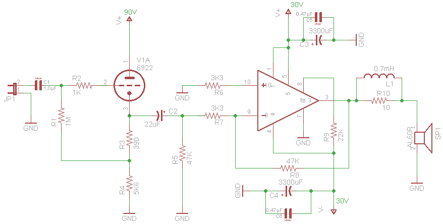
12AU7 cathode follower goes first. Then tone control like here:
An externally hosted image should be here but it was not working when we last tested it.
But without IC1, since CF does the job.
Then 10k volume pot. Then dual 10k pot for balance. Then noninverting LM3886.
What do you think?
Now playing waiting game for parts of eBay to come from Asian continents....
Thanks everyone for input. Will buy a beer if I visit your countries. 🙂
Thanks everyone for input. Will buy a beer if I visit your countries. 🙂
...What do you think?
This is OK.
I understood that the cathode follower is driving LM3886 directly.
Well, I will probably end up trying it first and then rearrange it to go before tone control, which might also change. I fill like it will be good project for me to expirement with sound and try to find what I like.
Yesterday I assembled my amplifier! It has audible ripple, but plays the music! 🙂 I suspect my power supply, but will have to check that in the nearest future.
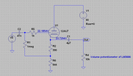
Here is the schematics of amp with exact elements I used:
For C2 I tried 20uF paper in oil, and 22uF electrolytic. Sound is the same between both.
Power supply schematics comes next.
Any hints why I hear the ripple?
Here is the schematics of amp with exact elements I used:
For C2 I tried 20uF paper in oil, and 22uF electrolytic. Sound is the same between both.
Power supply schematics comes next.
Any hints why I hear the ripple?
Yesterday I assembled my amplifier! It has audible ripple, but plays the music! 🙂
I suspect my power supply, but will have to check that in the nearest future. Any hints why I hear the ripple?
The 22uF electrolytic is connected backwards.
Many possibilities, can you post a schematic of the supply, and post a few pix of the layout?
A 0.1uF in front of the CF would be sufficient as well. !!C2 is shown connected backward!!
Not sure why you went for an inverting input configuration, driving a 3.3K load is a pretty big deal for your 12AU7A, I am not certain it can provide the required current. A non-inverting configuration makes more sense and would probably result in less output offset. For minimum offset R6 should be in the vicinity of 24K, which will result in significantly more noise than necessary.
- Status
- Not open for further replies.
- Home
- Amplifiers
- Tubes / Valves
- Calculating cathode follower using 12AU7 for 90V supply